
CEMP-E
TI 809-07
30 November 1998
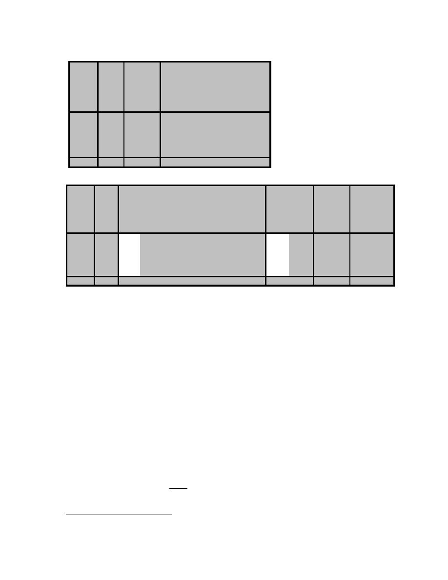
Table D-11. Column and Anchor Shear Design.
Column
Strap
Yield
Anchor
Total
Shear
Lat Ult
Stress of
Angle
Shear
Shear
Strength
Capacity
Angle
Thickness Strength Strength
Phumax=Ω 0QE
VC
FyA
tA
VA
VT
(kips)
(kips)
(ksi)
(in)
(kips)
(kips)
3rd Floor
4.7
16.0
36
0.250
32.4
69.5
3rd Floor*
11.8
20.5
36
0.250
32.4
76.6
2nd Floor
26.9
47.0
36
0.250
32.4
91.7
1st Floor
37.7
66.7
36
0.250
32.4
102.5
1st Floor*
50.2
63.5
36
0.250
32.4
115.0
1st Floor
62.1
57.4
36
0.500
64.8
191.7
Table D-12. Screwed Connection Design.
Max Est Nominal Diagonal Strap-to-Column Conn
Design Number
Bearing2 Nominal Screw
Nominal Manufacturer's Shear Screws
Ult Strap Screw
Strap/Col
Tilting
Bearing1
Force
Dia
Thickness Eq C-48 Eq C-49&51 Eq C-50&52 Shear head dia Pull-over Nom Shear /Screw /Face
Psu
Pns
Pns
Pns
Pns
dw
Pnov
Pns
Ps
nscrews
d
Ratio
(t2/t1)
(kips)
(in)
(kips)
(kips)
(kips)
(kips)
(in)
(kips)
(kips)
(kips)
(#)
3rd Floor
20.2
0.19
0.80
1.205
1.724
1.380
1.205
0.402
2.027
1.232
0.602
33
3rd Floor*
25.8
0.19
1.56
1.682
1.103
1.724
1.103
0.402
1.297
1.013
0.506
25
2nd Floor
60.5
0.19
1.00
2.430
1.724
2.491
1.724
0.402
2.027
1.242
0.621
49
1st Floor
84.7
0.19
1.00
4.026
2.415
3.488
2.415
0.402
2.838
1.242
0.621
68
1st Floor*
80.7
0.19
1.40
4.026
1.724
3.488
1.724
0.402
2.027
1.242
0.621
65
1st Floor
72.8
Minimum distance between centers of fasteners is 3d = 0.57 inches.
Minimum distance from centers of fasteners to edge of connected part is 3d = 0.57
inches.
For connections subjected to shear forces in only one direction, the minimum distance
from centers of fasteners to the edge of a connected part perpendicular to the force is
1.5d = 0.29 inches.
The design shear and pull-over per screw, Ps shall be calculated according to Equations C-47
through C-53 based on the thicknesses of the connected members. Table D-12 gives the ratio of t2/t1
and the resulting design shear per screw as defined by these equations. A screw head diameter, dw
of 0.402 inches11 is used for the #10 hex head screws.
Finally, the number of screws required at each diagonal strap-to-column connection, nscrews is
calculated according to Equation 3-16 for each trial panel configuration. These quantities are given in
Table D-12.
12
Ultimate shear values from the manufacturer' data , Pu based on the smaller thickness of the
s
members being connected are used to calculate a nominal screw shear strength, Pns according to the
following equation:
Pu
Pns =
(Eq D-25)
1.25
11
This dimension was measured from #10 hex washer head screws (ITW Buildex Part Number 1129000) used in test panels at
USACERL. Measurement was made using a Vernier caliper and the diameter at the base of the washer head was consistently
0.402 inches 0.004 inches (10.2 mm 0.1 mm).
12
From ITW Buildex Catalog for #10 fasteners with #3 drill point.
D-12

 Previous Page
