
CEMP-E
TI 809-07
30 November 1998
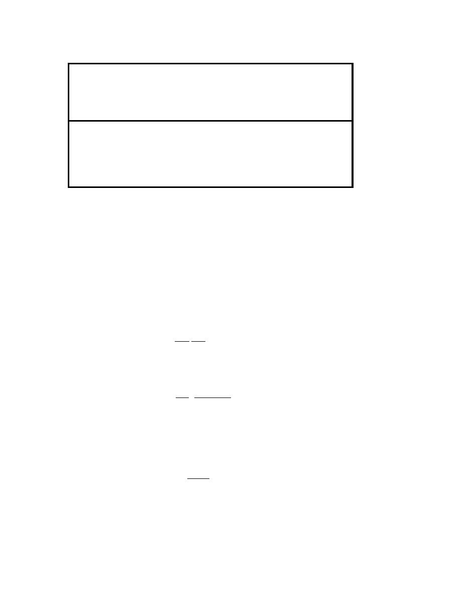
Table D-4. Long Direction Lateral Seismic Force Calculations for the Barracks Building.
Long
Long
Number
Long Dir
Long Dir
Direction
Seismic
Dir
Height
Vertical
Frames
Lateral
Seismic
Total
Response
Base
at Floor
Distribution
in Long
Seismic
Story
Panel
Weight
Coefficient
Shear
Level
Factor
Dir
Force/frame
Shear
Level
WL
Cs
VL
hxS or hxL
CvxL
nL
FxL
VxL
(k-mass)
(g)
(kips)
(ft)
(kips)
(kips)
Roof
3rd
247
27.042
0.271
2
42.713
42.713
Cumulative
247
2nd
647
18.583
0.488
2
76.983
119.696
Cumulative
894
1st
653
9.125
0.241
2
38.110
157.806
Cumulative
1547
0.204
316
D9. DIAGONAL STRAP DESIGN. From the values of seismic story shear, Vx (Vx + Qsi in Equation 3-
4) the shear panel diagonal straps are sized according to Equation 3-4. Values of the shear panel
design strength, φQsy are given in Table D-5. Two identical shear panels are used at each floor level,
t
and applied story shear in the short direction, VxS per shear panel are shown in Table D-5. Trial
shear panel dimensions and diagonal strap sizes for each floor level are defined so that the design
strength, φQsy exceeds the applied story shear, VxS per shear panel, using the spreadsheet program
t
that models Equation 3-4. Table D-5 shows trial shear panel configurations that meet this
requirement for each floor of the critical frame in the barracks building example. All diagonal straps
require ASTM 653, Grade 33 or Grade 50 steel. Panel dimensions are based on the dimensions
given for Shearwall Type " W-3"(Interior Load-Bearing Walls) of the barracks building drawings
S
(Sheet S-6).
The diagonal straps are the sole lateral-load-resisting element, and as such they determine the story
drifts. The elastic deflections, δe, at each floor level are calculated as follows:
x
δy VxS
δe = s
(Eq D-19)
x
Qsy nS
where δy is the lateral deflection at diagonal strap yielding given by:
s
Fsy H2 + W 2
δy =
(Eq D-20)
E W
s
Values of δe are given in Table D-5, for the trial diagonal straps at each floor level in the short
x
direction of the building. The design story drifts, ∆ are the differences in deflection at the center of
mass at the top and bottom of the story under consideration. These deflections are calculated from
the elastic deflection, δe as follows (from Equation C-29):
x
Cdδe
∆=δ=
x
(Eq D-21)
x
I
Where :
Cd = the deflection amplification factor given in Table D-1 (3.5 for diagonal strap panels).
I = the importance factor given in Table D-1 (1.0 for the barracks building).
Values for the design story drifts are given in Table D-5.
D-7

 Previous Page
