CEMP-E
TI 809-07
30 November 1998
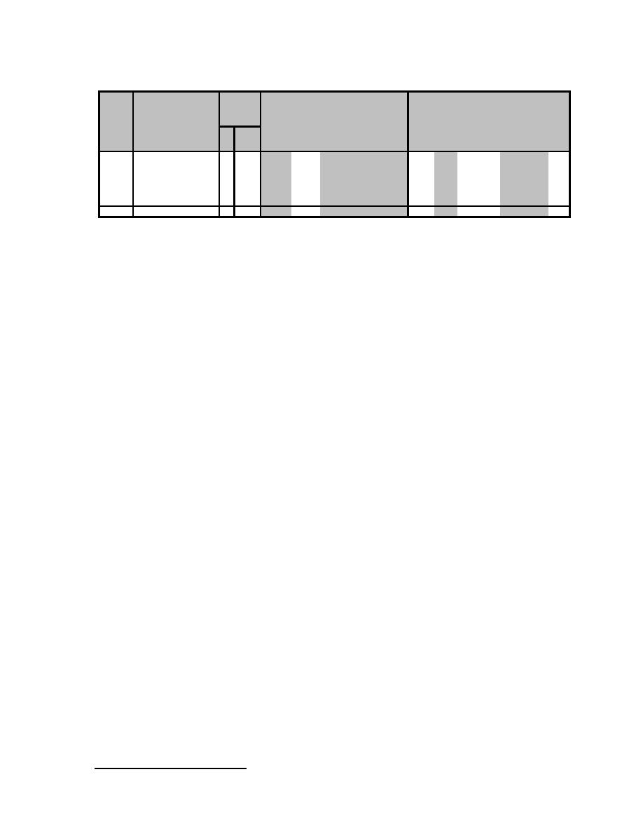
Table D-5. Diagonal Strap Design in the Short Direction.6
Strap
Yield
Strap
Design Lat Defl Applied Elastic Defl
Design
Allow
Panel Panel Strap Strap
Strap
Initial Lat Stress Lat Yield
Shear
at Strap
Story Lateral Amp Import Story Stability Story
Width Height Faces Width
Thickness Stiffness of Strap Capacity Strength Yielding Shear
Defl Factor Factor Drifts
Coeff
Drifts
φQsy
∆a
ns
bs
ts
ks
Fsy
Qsy
VxS
Cd
δy
δe
∆
θ
W
H
I
t
s
x
(in)
(in)
(#)
(in)
(ga)
(in)
(k/in)
(ksi)
(k)
(k)
(in)
(kips)
(in)
(in)
(in)
3rd Floor
132 101.5
1
4
14 0.0747
41
33
7.8
7.4
0.239
6.71
0.205
3.5
1.0
0.718 0.0008
2.03
3rd Floor*
132 101.5
2
4
18 0.0478
53
33
10.0
9.5
0.239
6.71
0.160
3.5
1.0
0.561 0.0006
2.03
2nd Floor
140 113.5
2
6
14 0.0747
112
33
23.0
21.8
0.264
18.52
0.213
3.5
1.0
0.745 0.0015
2.27
1st Floor
140 109.5
2
6
12 0.1046
161
33
32.6
31.0
0.257
24.38
0.192
3.5
1.0
0.672 0.0020
2.19
1st Floor*
140 109.5
2
8
14 0.0747
154
33
31.1
29.5
0.257
24.38
0.201
3.5
1.0
0.705 0.0021
2.19
1st Floor
140 109.5
2
6
14 0.0747
115
50
35.3
33.5
0.389
24.38
0.269
3.5
1.0
0.94
0.0029
2.19
Increases in design story drift, ∆ related to P-delta effects are now evaluated. P-delta effects do not
need to be considered if the stability coefficient, θ is equal to or less than 0.10. The stability
coefficient, θ is defined in Equation C-30 and values are given in Table D-5. These values are well
below 0.10, so design story drifts do not need to be increased. Values of design story drifts, ∆ must
be less than the allowable story drifts, ∆a given in Table 3-2. For the barracks building this may be
expressed as follows (from Table 3-2):
∆a = 0.020H
(Eq D-22)
Values of design story drift, ∆ and allowable story drift, ∆a are given in Table D-5 for each floor level
for the trial panels in the short direction of the barracks building. The values in Table D-5 show that
design story drifts fall below allowable drifts by almost a factor of 3. Therefore these trial sizes meet
the drift requirements.
D10. COLUMN DESIGN. Columns are either built-up from studs (Panel A configuration) or are
structural tubes (Panel D). The columns built up with cold-formed steel studs must have the studs
oriented to form a closed cross-section as shown on Drawings A1 and A2 in Appendix B. Individual
studs must be welded to each other with a weld thickness equal to the thickness of the studs. The
welds are intermittent, with a length and spacing that will ensure composite behavior of the columns.
Structural tubing columns consist of a single tube, which is a closed section by itself. This column will
provide greater moment resistance because of the heavier anchorage detail, and will provide a
greater degree of structural redundancy and widening of the shear panel hysteretic performance.
a. Column Applied Loads. Total load applied to the entire building in the short direction is
expressed by Equation C-17, where the effects of gravity load and seismic forces are additive and
diagonal strap overstrength is accounted for. In this example snow loads, S are zero. This equation
can be expressed in terms of the total dead load, DT, and live load, L, given in Table D-2, as follows:
(1.2 + 0.2SDS )DT + 0.5L + Ω 0QE
(Eq D-23)
The loads expressed in Equation D-23 are now divided between the number of frames that make up
the short-direction lateral-load-resisting system. The barracks building has a total of nine such
frames. The loads are distributed based on the tributary area of each frame. Because the end bays
have only half the tributary area, the loads are divided by the number of frames minus one, or also
stated as the number of bays as seen in Table D-6. The vertical load resisting members are the
shear panel columns and individual studs, and these are distributed fairly uniformly in plan throughout
the building. It is assumed that vertical loads are distributed to these studs in proportion to their area,
because of the uniform distribution of columns and individual studs in throughout the building in plan
(normally gravity loads would be distributed based on tributary area).
6
Asterisk designates selected straps.
D-8


 Previous Page
