TM 5-809-3/NAVFAC DM-2.9/AFM 88-3, Chap. 3
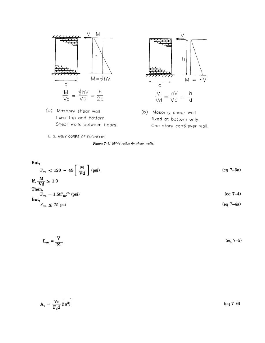
The ratio of M/(Vd) will always be taken as a positive number. The values of Fvm and Fvs may be increased
by a factor of 1.33 when wind or seismic loads are considered in the loading combination.
7-4. Design Considerations.
a. Shear Stresses. The calculated shear stress, fvm, will be determined as follows:
Where:
V = The total shear load, pounds.
t = The actual thickness of shear wall section for solid grouted masonry or the equivalent thickness
of a partially grouted hollow masonry wall, inches. (See Chapter 5 for the equivalent thicknesses).
d = The actual length of the shear wall element, inches.
(To be more exact, the actual wall panel length minus the tension reinforcement cover distance may be used).
When the allowable shear stress, Fvm, is exceeded, horizontal and vertical shear reinforcement must be
provided. The horizontal shear steel will be designed to carry the entire in-plane shear force. The area of
shear reinforcement, Av, will be determined as follows:
Where:
s = The spacing of the shear reinforcement, inches.
Fs = the allowable tensile stress in the reinforcement, psi.
7-2


 Previous Page
