TM 5-809-3/NAVFAC DM-2.9/AFM 88-3, Chap. 3
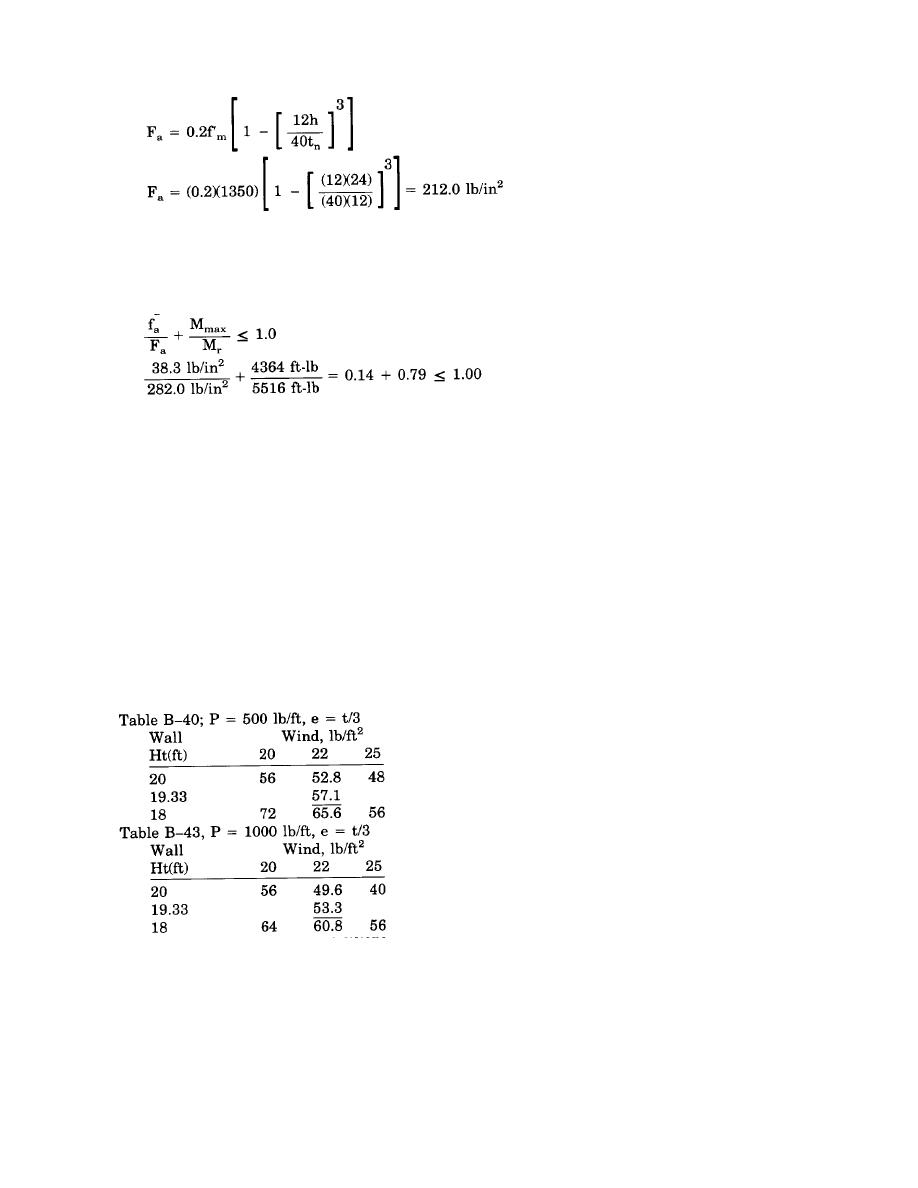
fa = 38.3 lb/in2 < Fa = 212.0 lb/in2
...O.K.
Combined Load Check: Since the masonry resisting moment controls, only the masonry need be checked in
the combined stress condition. The unity equation will be used. Since wind loadings `are a part of the loading
combination, the allowable axial compressive stress, Fa, may be increased by 33%.
Fa = 1.33(212.0 lb/in2) = 282.0 lb/in2
...O.K.
Direct solution (table B-47): Using the design parameters given above; the 1-#6 bar spaced at 24 inches o.c.
which was determined by the design calculations; is sufficient reinforcement.
(4) Summary. 1-#6 bar per cell spaced at 24 inches o.c. is sufficient.
b. Design example 2. This illustrative example considers only one combination of wind and eccentric axial
loading. When performing a complete wall design, all appropriate load combinations must be considered.
(1) Given:
(a) 12-inch CMU wall
(b) Wall height (h) = 19*-4"
(c) Lateral wind load (w) = 22 lb/ft2
(d) Axial load (P) = 650 lb/ft
(e) Eccentricity (e) = t/3
(f) f*m = 1350 lb/in2
(g) Fs = 24,000 lb/in2
(2) Problem. Find the required spacing of #6 bars using the tables in appendix B and linear
(3) Solution. Interpolating for wall height, axial loading, and wind loading.
Smax = 57.1 - (57.1 - 53.3)[(650 - 500)/500] = 56 inches o.c.
(4) Summary. The wall will resist the given loading with #6 bars spaced at 56 inches on center.
c. Design example 3. This illustrative example considers only one combination of wind and eccentric axial
loading. When performing a complete wall design, all appropriate load combinations must be considered.
(1) Given.
(a) 8-inch CMU wall
(b) Wall height (h) = 16 ft
(c) Wall length (L) = 30 ft
6-7


 Previous Page
