TM 5-809-3/NAVFAC DM-2.9/AFM 88-3, Chap. 3
CHAPTER 7
REINFORCED MASONRY SHEAR WALLS
7-1. Introduction. This chapter contains design requirements for reinforced masonry shear walls, not
including seismic requirements. Requirements for shear walls in buildings located in seismic zones 1 through
4 are given in TM 5-809-10/NAVFAC P-355/AFM 88-3, Chapter 13, Seismic Design for Buildings. Except
as contained herein, design criteria, section properties, material properties, design equations, and allowable
stresses are contained in chapter 5.
7-2. General. A masonry shear wall is any masonry wall, external or internal, which resists externally applied
in-plane horizontal forces. A shear wall is a vertical element in the building lateral load resisting system. It
transfers horizontal forces vertically downward from a diaphragm above to a diaphragm or a foundation
below. Thus, horizontal wind or seismic forces are collected at floor or roof diaphragm levels and transferred
to the building foundation by the strength and rigidity of the shear walls. A shear wall may be considered
analogous to a plate girder cantilevered off the foundation in a vertical plane. The wall performs the function
of a plate girder web and the integral vertical reinforcement at the ends of wall panels, between control joints,
function as the beam flanges. Pilasters or floor diaphragms, if present, function as web stiffeners. Axial,
flexural, and shear forces must be considered in the design of shear walls, including the tensile and
compressive axial stresses resulting from loads tending to overturn the wall.
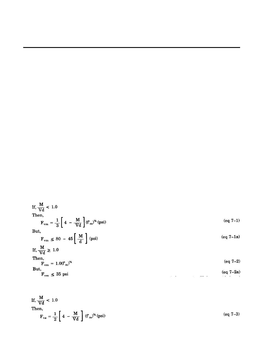
7-3. Allowable shear stresses. The allowable shear stress in a shear wall is dependent upon the magnitude
of the ratio of M/(Vd), where M is the maximum moment applied to the wall due to the in-plane shear force,
V, and d is the effective length of the wall. Therefore, if the shear wall is assumed fixed at the top and bottom
(a multistory shear wall), M = hV, and M/(Vd) becomes h/2d, where h is the height of wall. However, if
the shear wall is assumed fixed at the bottom only, (a single-story cantilevered shear wall), M = hV, and
M/Vd becomes h/d. Figure 7-1 illustrates these conditions.
The allowable shear stress is also dependent upon whether or not shear reinforcement is provided. If the
calculated shear stress, fvm, exceeds the allowable shear stress, Fvm, then shear reinforcement will be provided.
The shear reinforcement will be designed to carry the entire shear force. The following equations illustrate
the limitations and requirements of determining the allowable shear stress in a shear wall.
a. No shear reinforcement provided. The calculated shear stress, fvm, shall not exceed the allowable shear
stress, Fvm.
b. Shear reinforcement provided. When firm exceeds Fvm, shear reinforcement will be provided and
designed to carry the entire shear force. The calculated shear stress in the reinforcement, fvm, shall not
exceed the allowable shear stress, Fvs.
7-1


 Previous Page
