TM 5-809-3/NAVFAC DM-2.9/AFM 88-3, Chap. 3
elements linked by connecting beams, the wall will be analyzed accordingly. It is common for openings to
occur in regularly spaced vertical rows (or piers) throughout the height of the wall with the connections
between the wall sections within the element being provided by either connecting beams (or spandrels) which
form a part of the wall, or floor slabs, or a combination of both. If the openings do not line up vertically
and/or horizontally, the complexity of the analysis is greatly increased. In most cases, a rigorous analysis of
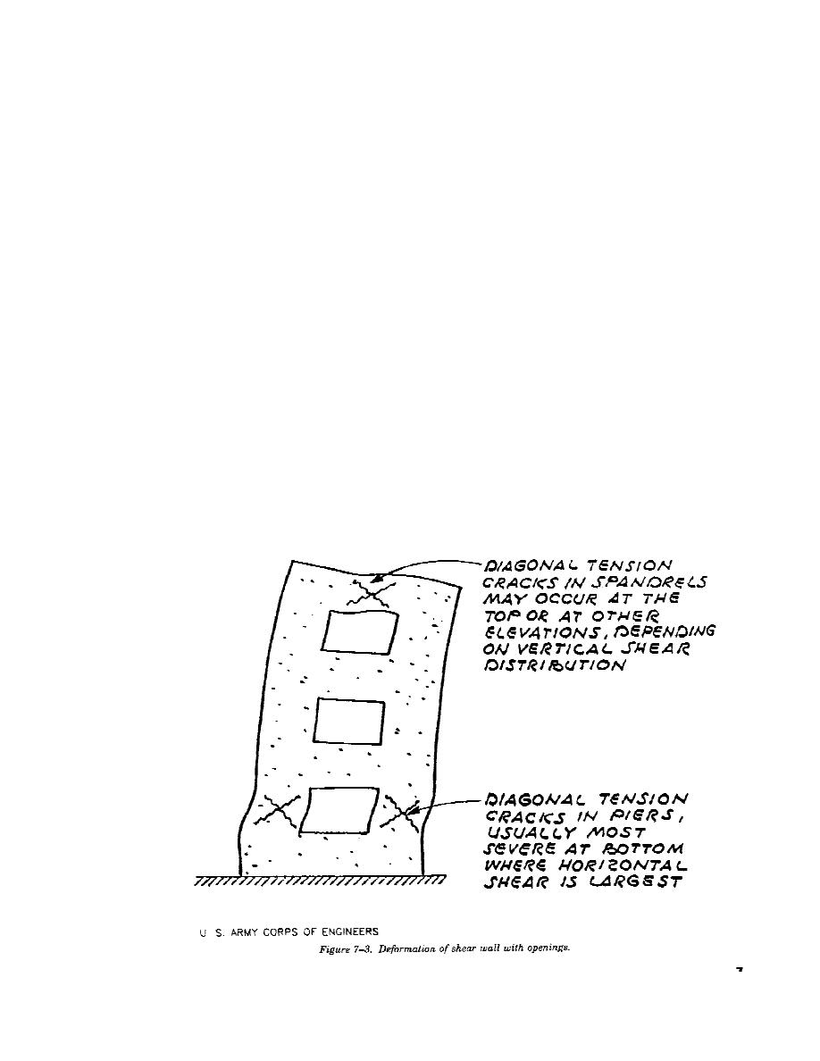
a wall with openings is not required. When designing a wall with openings, the deformations must be
visualized in order to establish some approximate method to analyze the stress distribution of the wall. Figure
7-3 gives a visual description of such deformations. The major points that must be considered are; the
lengthening and shortening of the extreme sides (boundaries) due to deep beam action, the stress
concentration at the corner junctions of the horizontal and vertical components between openings, and the
shear and diagonal tension in both the horizontal and vertical components.
a. Relative rigidities of piers and spandrels. The ease of analysis for walls with openings is greatly
dependent upon the relative rigidities of the piers and spandrels, as well as the general geometry of the
building. Figure 7-4 shows two extreme examples of relative rigidities of exterior walls of a building. In figure
7-4(a) the piers are very rigid relative to the spandrels. Assuming a rigid base, the shear walls act as vertical
cantilevers. When a lateral force is applied, the spandrels act as struts with end moments-thus the flexural
deformation of the struts must be compatible with the deformation of the cantilever piers. It is relatively
simple to determine the forces on the cantilever piers by ignoring the deformation characteristics of the
spandrels. The spandrels are then designed to be compatible with the pier deformations. In figure 7-4(b), the
piers are flexible relative to the spandrels. In this case, the spandrels are assumed to be infinitely rigid and the
piers are analyzed as fixed-end columns. The spandrels are then designed for the forces induced by the
columns. The calculations of relative rigidities for both cases shown in figure 7-4 can be aided by the use of
the wall deflection charts given later in this chapter. For cases of relative spandrel and pier rigidities other
than those shown, the analysis and design becomes more complex.
b. Methods of Analysis. As stated above, approximate methods of analyzing walls with openings are
generally acceptable. A common method of determining the relative rigidity of a shear wall with openings
is given in the design example in this chapter. For the extreme cases shown in figure 7-4, the procedure is
straight-forward. For other cases, a variation of assumptions may be used to determine the most critical
7-5


 Previous Page
