TM 5-809-3/NAVFAC DM-2.9/AFM 88-3, Chap. 3
Horizontal shear reinforcement will be uniformly distributed over the full height of the wall. Shear
reinforcement will consist of deformed bars, thus joint reinforcement that is in the wall to control cracking
will not be considered as shear reinforcement. The vertical spacing of shear reinforcement will not exceed
the lessor of d/2 or 48 inches. Shear reinforcement will be terminated with a standard hook or will have an
embedment length beyond the vertical reinforcing at the end of the wall panel. The hook or embedded
extension will be turned up, down, or extended horizontally. Vertical deformed bar reinforcement that is at
least equal to one-third Av will be provided in all walls requiring shear reinforcement. This vertical
reinforcement will be uniformly distributed and will not exceed a spacing of 48 inches.
b. Shear stresses from seismic loadings. When designing shear walls for buildings in seismic zones 1
through 4, the increase in the seismic shear forces required in TM 5-809-10/NAVFAC P-355/AFM 88-3,
Chapter 13 will be included.
c. Other shear wall stresses.
(1) The axial stresses caused by dead and live loads from roofs and floors will be considered in design
of shear walls.
(2) The flexural stresses caused by moments from lateral in-plane shear force applied to the top of the
wall or by the diaphragm will also be consideration in design. This in-plane moment is Vh for cantilever shear
walls with fixed ends.
(3) The combined effects of axial and bending stresses must be considered. The unity equation or other
methods using accepted principles of mechanics will be used.
7-5. Rigidity.
a. General. The magnitude of the total lateral forces at any story level depends upon the structural system
as a whole. Also, the proportion of the total horizontal load that is carried by a particular shear wall element
is based on the rigidity of the wall element relative the combined rigidities of all the wall elements on that
same level. The relative rigidities of shear wall elements are inversely proportional to their deflections when
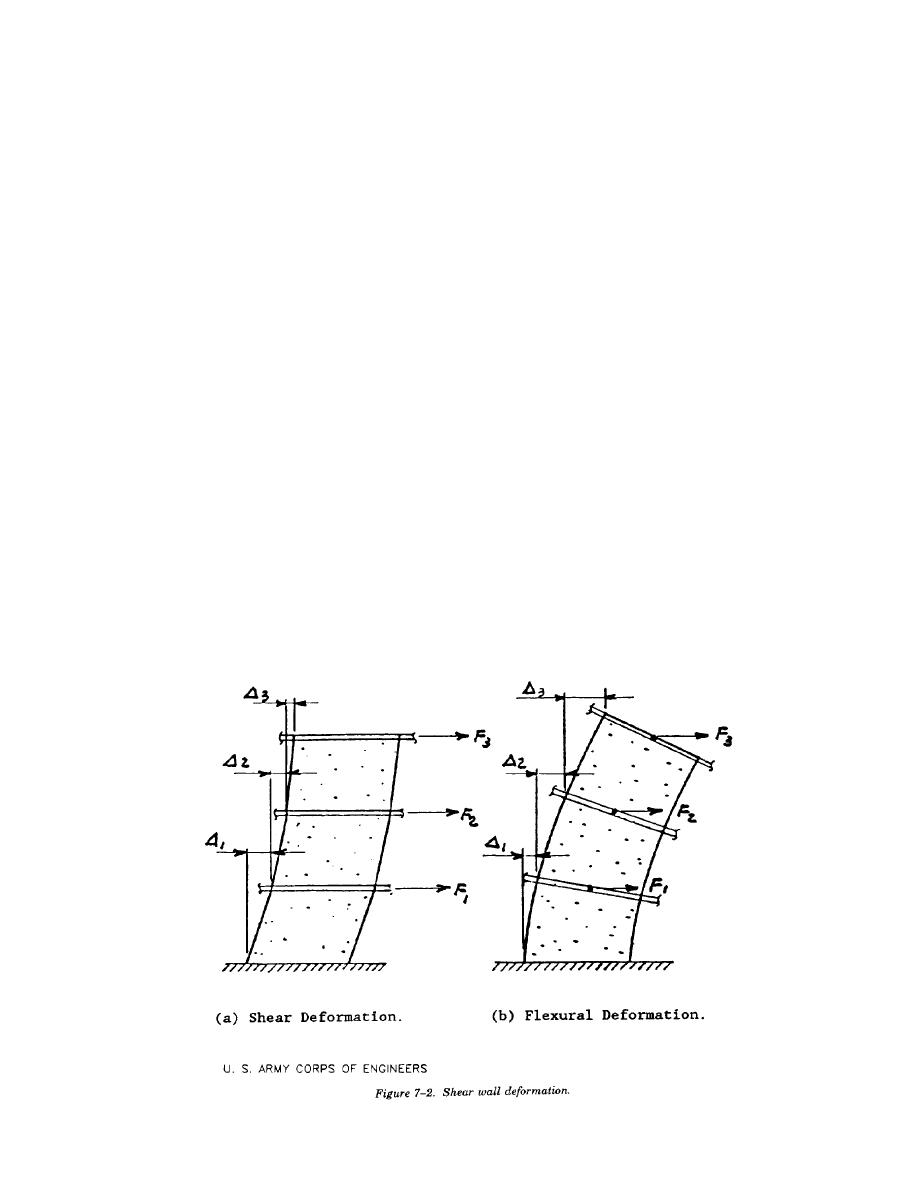
loaded with a unit horizontal force. The total deflection at the top of a shear wall element is the sum of the
shear deformation and flexural deflection (Figure 7-2) plus any additional displacement that may occur due
to rotation at the base. For most shear walls in ordinary buildings, shear deformation is the major contributor
to in-plane deflection.
b. Factors affecting rigidity.
(1) Control joints are complete structural separations that break the shear wall into elements. The
elements must be considered as isolated structural members during shear wall rigidity analyses. The number
7-3


 Previous Page
