TM 5-818-5/AFM 88-5, Chap 6/NAVFAC P-418
ing surging, and recleaned after surging is completed.
g. After the wells are developed and satisfactorily
Material bailed from a well should be inspected to see
tested by pumping, the pumps, power unite, and dis-
if any foundation sand is being removed. It is possible
charge piping may be installed.
to oversurge a well, which may breach the filter with
h. Where drawdown or vacuum requirements in
resulting infiltration of foundation sand when the well
deep wells demand that the water level be lowered and
is pumped.
maintained near the bottom of the wells, the pumps
e. After a well has been developed, it should be
will have to handle a mixture of water and air. If such
pumped to clear it of muddy water and sand and to
a requirement exists, the pump bowls should be de-
check it for yield and infiltration. The well should be
signed to allow increasing amounts of air to enter the
pumped at approximately the design discharge from
bowl, which will reduce the efficiency of the pump un-
30 minutes to several hours, with periodic measure-
til the pump capacity just equals the inflow of water,
ment of the well flow, drawdown in the well, depth of
without cavitation of the impellers. The impellers of
sand in the bottom of the well, and amount of sand in
deep-well turbine pumps should be set according to the
the discharge. Measurements of well discharge and
manufacturer's recommendations. Improper impeller
drawdown may be used to determine the efficiency
settings can significantly reduce the performance of a
and degree of development of the well. The perfor-
deep-well pump.
mance of the well filter may be evaluated by measur-
5-3. Wellpoint systems.
ing the accumulation of sand in the bottom of the well
and in the discharge. A well should be developed and
a. Wellpoint systems are installed by first laying
pumped until the amount of sand infiltration is less
the header at the location and elevation called for by
than 5 to 10 parts per million.
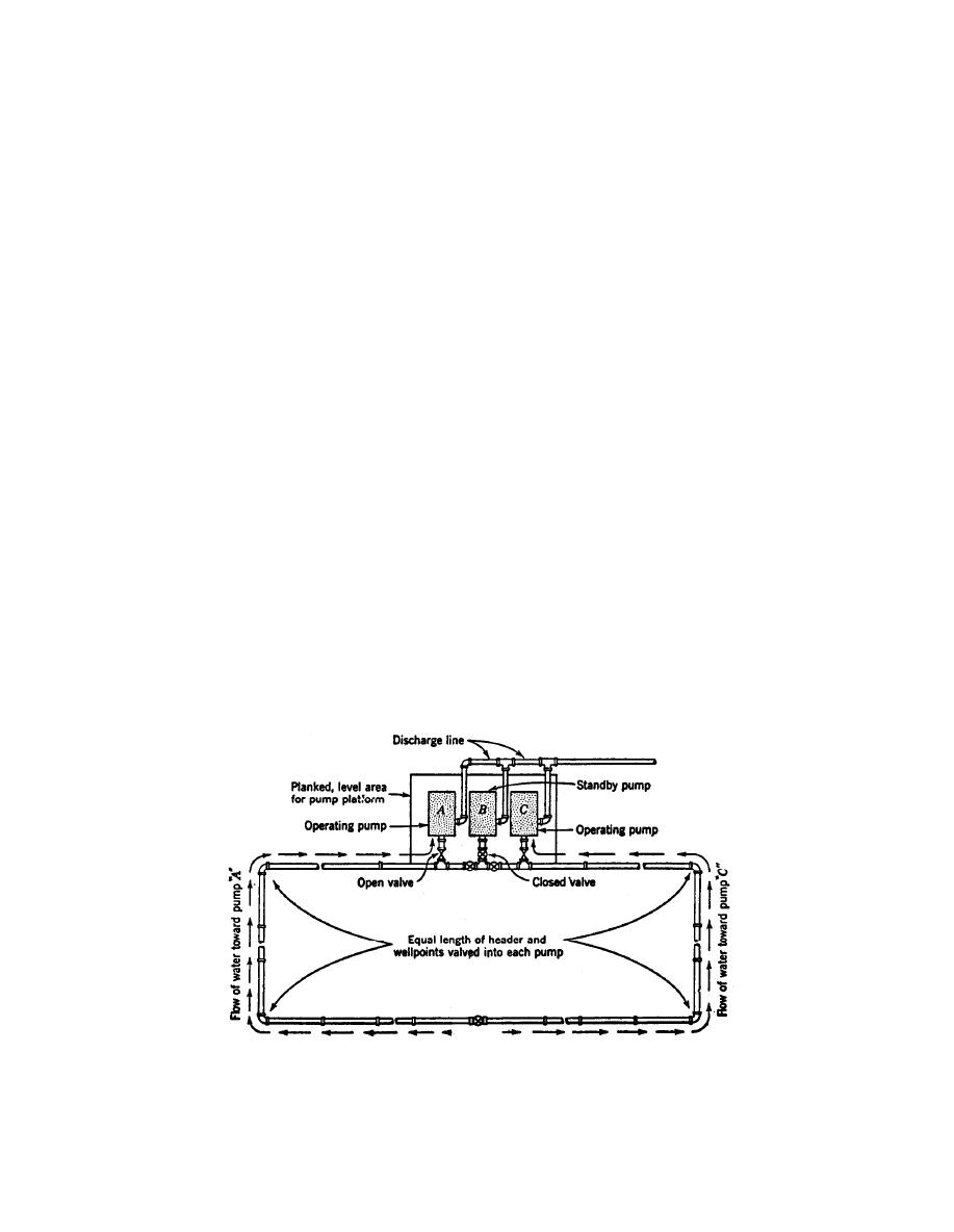
the plans as illustrated in figure 5-1. After the header
pipe is laid, the stopcock portion of the swing connec-
f. Deep wells, in which a vacuum is to be main-
tion should be connected to the header on the spacing
tained, require an airtight seal around the well riser
called for by the design, and all fittings and plugs in
pipe from the ground surface down for a distance of 10
the header made airtight using a pipe joint compound
to 50 feet. The seal may be made with compacted clay,
to prevent leakage. Installation of the wellpoints gen-
nonshrinking grout or concrete, bentonitic mud, or a
erally follows layout of the header pipe.
short length of surface casing capped at the top. Im-
proper or careless placement of this seal will make it
b. Self-jetting wellpoints are installed by jetting
impossible to attain a sufficient vacuum in the system
them into the ground by forcing water out the tip of
to cause the dewatering system to operate as designed.
the wellpoint under high pressure. The jetting action
The top of the well must also be sealed airtight.
of a typical self-jetting wellpoint is illustrated in fig-
Plan of a typical wellpoint system.
(From "Foundation Engineering," G. A. Leonards, ed., 1962, McGraw-Hill Book
Company. Used with permission of McGraw-Hill Book Company.)
Figure 5-1. Plan of a typical wellpoint system.
5-2


 Previous Page
