TM 5-818-5/AFM 88-5, Chap 6/NAVFAC P-418
so that the dewatering wells and pumps cannot be
into the excavation or from the drainage area into the
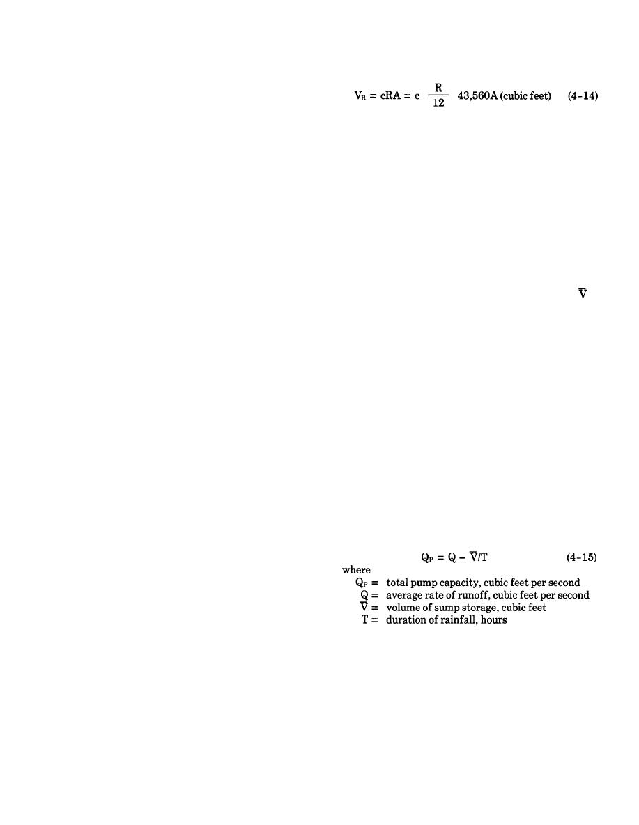
flooded. Control of surface water within the diked area
excavation from the equation
will not only prevent interruption of the dewatering
operation, which might seriously impair the stability
of the excavation, but also prevent damage to the con-
where
struction operations and minimize interruption of
c = coefficient of runoff
work. Surface water may be controlled by dikes,
R = rainfall for assumed rainstorm, inches
ditches, sumps, and pumps; the excavation slope can
A = area of excavation plus area of drainage into
be protected by seeding or covering with fabric or as-
excavation, acres
phalt. Items to be considered in the selection and de-
(The value of c depends on relative porosity, character,
sign of a surface water control system include the dur-
and slope of the surface of the drainage area. For im-
ation and season of construction, rainfall frequency
pervious or saturated steep excavations, c values may
and intensity, size of the area, and character of surface
be assumed to range from 0.8 to 1.0.)
soils.
Step 4. Plot values of VR versus assumed dura-
tion of rainstorm.
used for design depends on the geographical location,
Step 5. Plot pumpage rate of pump to be in-
risk associated with damage to construction or the de-
stalled assuming pump is started at onset of rain.
watering system, and probability of occurrence during
This method is illustrated by figure D-10.
construction. The common frequency of occurrence
g. The required ditch and sump storage volume
is
used to design surface water control sumps and pumps
the (maximum) difference between the accumulated
is a once in 2-to 5-year rainfall. For critical projects, a
runoff for the various assumed rainstorms and the
frequency of occurrence of once in 10 years may be ad-
amount of water that the sump pump (or pumps) will
visable .
remove during the same elapsed period of rainfall. The
d. Impounding runoff on excavation slopes is some-
capacity and layout of the ditches and sumps can be
what risky because any overtopping of the dike could
adjusted to produce the optimum design with respect
result in overtopping of all dikes at lower elevations
to the number, capacity, and location of the sumps and
with resultant flooding of the excavation.
pumps.
h. Conversely, the required capacity of the pumps
e. Ample allowance for silting of ditches should be
for pumping surface runoff depends upon the volume
made to ensure that adequate capacities are available
of storage available in sumps, as well as the rate of
throughout the duration of construction. The grades of
runoff (see equation (3-3)). For example, if no storage
ditches should be fairly flat to prevent erosion. Sumps
is available, it would be necessary to pump the runoff
should be designed that will minimize siltation and
at the rate it enters the excavation to prevent flooding.
that can be readily cleaned. Water from sumps should
This method usually is not practicable. In large excava-
not be pumped into the main dewatering system.
tions, sumps should be provided where practicable to
f. The pump and storage requirements for control of
reduce the required pumping capacity. The volume of
surface water within an excavation can be estimated in
sumps and their effect on pump size can be determined
the following manner:
graphically (fig. D-10) or can be estimated approxi-
Step 1. Select frequency of rainstorm for which
mately from the following equation:
pumps, ditches, and sumps are to be designed.
Step 2. For selected frequency (e.g., once in 5
years), determine rainfall for 10-, 30-, and 60-minute
rainstorms at project site from figure 3-6.
Step 3. Assuming instantaneous runoff, com-
pute volume of runoff VR (for each assumed rainstorm)
4-50


 Previous Page
