TM 5-818-5/AFM 88-5, Chap 6/NAVFAC P-418
using a hole puncher and a jet casing to form the hole
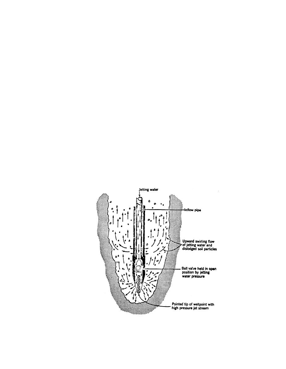
ure 5-2. Self-jetting wellpoints can be installed in me-
for the wellpoint and filter. When the wellpoint reach-
dium and fine sand with water pressures of about 50
es grade and before the water is turned off, the two
pounds per square inch. Wellpoints jetted into coarse
halves of a swing connection, if used, should be lined
sand and gravel require considerably more water and
up for easy connection when the jet water is turned off
higher water pressures (about 125 pounds per square
and the jetting hose disconnected.
inch) to carry out the heavier particles; either a hy-
drant or a jetting pump of appropriate size for the
c. Where a wellpoint is to be installed with a filter
pressures and quantities of jetting water required can
(i.e. "sanded"), generally the wellpoint should be in-
be used. The jetting hose, usually 2 to 3 inches in diam-
stalled in a hole formed by jetting down a 10- to 12-
eter, is attached to the wellpoint riser, which is picked
up either by a crane or by hand and held in a vertical
inch heavy steel casing. The casing may be fitted with
a removable cap at the top through which air and wat-
position as the jet water is turned on. The wellpoint is
er may be introduced. The casing is jetted into the
allowed to sink slowly into the ground and is slowly
ground with a return of air and water along the out-
raised and lowered during sinking to ensure that all
side of the casing. Jetting pressures of 125 pounds per
fine sand and dirt are washed out of the hole. Care
square inch are commonly used; where resistant strata
should be taken to ensure that a return of jet water to
are encountered, the casing may have to be raised and
the surface is maintained; otherwise, the point may
dropped with a crane to chop through and penetrate to
"freeze" before it reaches grade. If the return of jet wa-
the required depth. A casing may also be installed us-
ter disappears, the point should be quickly raised until
ing a combination jetting and driving tool, equipped
circulation is restored and then slowly relowered. In
with both water and air lines, which fits inside the cas-
gravelly soils, it may be necessary to supplement the
ing and extends to the bottom of the casing. Most of
jet water with a separate air supply at about 125
the return water from a `hole puncher" rises inside the
pounds per square inch to lift the gravel to the surface.
casing, causing considerably less disturbance of the ad-
If filter sand is required around the wellpoint to in-
jacent foundation soils. After the casing is installed to
crease its efficiency or prevent infiltration of founda-
a depth of 1 to 3 feet greater than the length of the as-
tion soils, the wellpoints generally should be installed
(Courtesy of Griffin Wellpoint Corp.)
Figure 5-2. Self-jetting wellpoint.
5-3


 Previous Page
