TM 5-818-5/AFM 88-5, Chap 6/NAVFAC P-418
are often wasted in construction; they are sometimes
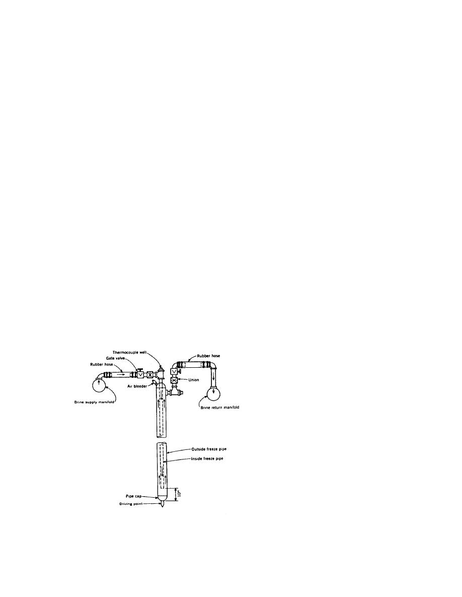
coolant flows slowly up the annulus between the pipes,
used for thawing the soil back to normal, in which case
pulls heat from the ground, and progressively freezes
they could be pulled afterward.
the soil. (A typical freeze-pipe is shown in fig. 4-37.)
After a week or two, the separate cylinders of frozen
d. Important considerations. The following items
soil join to form the barrier, which gradually thickens
must be considered when the freezing technique is to
to the designed amount, generally at least 4 feet (walls
be used:
of 24-foot thickness with two rows of freeze-pipes have
(1) Water movement in soil.
been frozen in large and deep excavations in soft or-
(2) Location of freeze-pipes. (The spacing of
ganic silts). The total freeze-time varies from 3 to 4
freeze-pipes should not exceed the designed amount by
weeks to 6 months or more but is predictable with high
more than 1 foot anywhere along the freeze wall.)
accuracy, and by instrumentation and observation the
(3) Wall closure. (Freeze-pipes must be accurately
engineer has good control. Sands of low water content
located, and the temperature of the soil to be frozen
freeze fastest; fine-grained soils of high water content
carefully monitored with thermocouples to ensure 100
take more time and total energy, although the refriger-
percent closure of the wall. Relief wells located at the
ation horsepower required may be greater than for
center of a shaft may also be used to check the prog-
sands.
ress of freezing. By periodically pumping these wells,
(2) The coolant is commonly a chloride brine at
the effectiveness of the ice wall in sealing off seepage
zero to -20 degrees Fahrenheit, but lower tempera-
flow can be determined.)
tures are preferable for saving time, reducing the
(4) Frost-heave effects-deformations and pres-
amount of heat to be extracted, and minimizing frost-
sures. (Relief wells may be used to relieve pressures
heave effects (which must be studied beforehand). In
caused by expansion of frozen soil.)
recent years, liquid propane at -45F has been used
(5) Temperature effects on buried utilities.
in large projects, and for small volumes of soil, liquid
(6) Insulation of aboveground piping.
nitrogen that was allowed to waste has been used.
(7) Control of surface water to prevent flow to the
(These cryogenic liquids demand special care-they are
freezing region.
dangerous.) Coolant circulation is by headers, com-
(8) Coolant and ground temperatures. (By moni-
monly 8-inch pipes, connected to a heat-exchanger at
toring coolant and soil temperatures, the efficiency of
the refrigeration plant using freon (in a modern plant)
the freezing process can be improved.)
as the refrigerant. The refrigeration equipment is us-
(9) Scheduling of operations to minimize lost time
ually rented for the job. A typical plant requires from
when freezing has been completed.
50 horsepower and up; 1000 horsepower or more has
(10) Standby plant. (Interruption of coolant circu-
sometimes been used. Headers should be insulated and
lation may be serious. A standby plant with its own
are recoverable. Freeze-pipes may be withdrawn but
prime movers is desirable so as to prevent any thaw. A
continuous advance of the freezing front is not neces-
sary so that standby plant capacity is much less than
that normally used.)
4-13. Control of surface water.
a. Runoff of surface water from areas surrounding
the excavation should be prevented from entering the
excavation by sloping the ground away from the exca-
vation or by the construction of dikes around the top
of the excavation. Ditches and dikes can be construct-
ed on the slopes of an excavation to control the runoff
of water and reduce surface erosion. Runoff into slope
ditches can be removed by pumping from sumps in-
stalled in these ditches, or it can be carried in a pipe or
lined ditch to a central sump in the bottom of the exca-
vation where it can be pumped out. Dikes at the top of
an excavation and on slopes should have at least 1 foot
of freeboard above the maximum elevation of water to
be impounded and a crown width of 3 to 5 feet with
side slopes of 1V on 2-2.5H.
(From "Tunnel Driven Using Subsurface Freezing. "by C. P. Gail, pp. 37-40.
Civil Engineering. American Society of Civil Engineers. May 1972.)
b. In designing a dewatering system, provision must
be made for collecting and pumping out surface water
Figure 4-37. Typical freeze-pipe.
4-49


 Previous Page
