TM 5-818-5/AFM 88-5, Chap 6/NAVFAC P-418
possible vacuum, the suction intake of the pump
sembled wellpoint, the jet is allowed to run until the
should be set level with the header pipe. Wellpoint
casing is flushed clean with clear water.
pumps should be protected from the weather by a shel-
d. The wellpoint is placed in the casing, the sand fil-
ter and from surface water or sloughing slopes by
ter tremied or poured in, and the casing pulled. Care
ditches and dikes. The discharge pipe should be water-
should be taken to center the wellpoint in the casing so
tight and supported independently of the pump.
that it is completely surrounded with filter material.
Before the wellpoint is connected to the header, it
f. Vacuum wellpoint systems are installed in the
same manner as ordinary wellpoint systems using a jet
should be pumped to flush it and the filter and to
casing and filter, except the upper 5 feet of the riser is
check it for "sanding." All joints connecting wellpoints
sealed airtight to maintain the vacuum in the filter.
to the header should be made airtight to obtain the
maximum needed vacuum.
g. Jet-eductor wellpoints are usually installed using
a hole puncher and surrounding the wellpoint and ris-
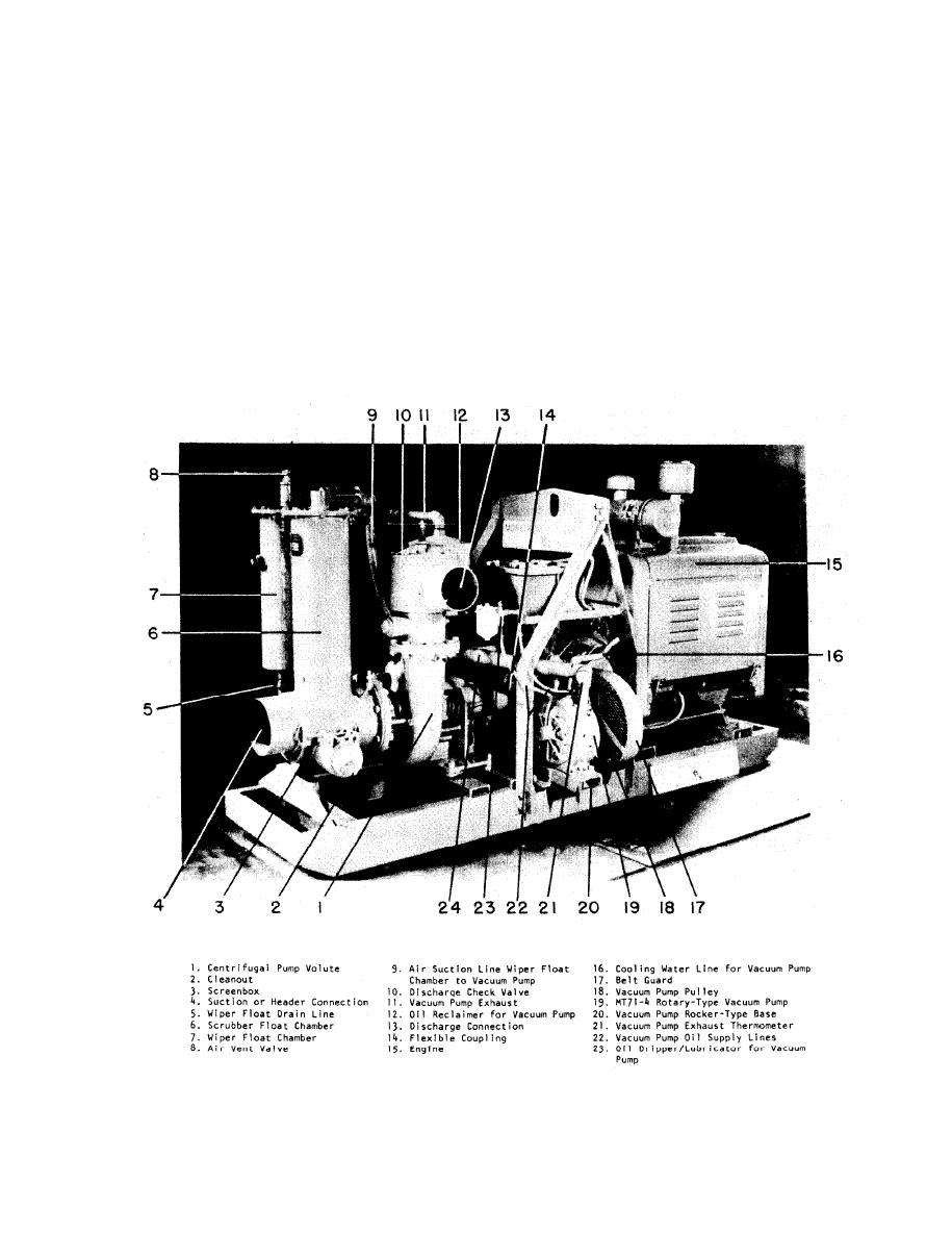
e. Wellpoint pumps, similar to that shown in figure
er pipe with filter sand. Jet eductors are connected to
5-3, are used to provide the vacuum and to remove
water flowing to the system. To obtain the maximum
two headers-one for pressure to the eductors and
(Courtesy of Moretrench American Corp.)
Figure 5-3. Characteristic parts of a wellpoint pump.
5-4


 Previous Page
