TM 5-818-5/AFM 88-5, Chap 6/NAVFAC p-418
tem can be designed to lower the water table below the
with sand or weighting material added: The viscosity
tunnel or bottom of the shaft using methods and for-
of the slurry for excavating slurry wall trenches usual-
mulas presented in paragraphs 4-1 through 4-4. If the
ly ranges from a Marsh funnel reading of 65 to 90 sec-
soil or rock formation is stratified, the wells must be
onds, as required to hold any weighting material add-
screened and filtered through each pervious stratum,
ed and to prevent any significant loss of slurry into the
as well as spaced sufficiently close so that the residual
walls of the trench. The slurry should create a pressure
in the trench approximately equal to 1.2 times the ac-
head in each stratum being drained is not more than 1
or 2 feet. Dewatering stratified soils penetrated by a
tive earth pressure of the surrounding soil. Where the
shaft or tunnel by means of deep wells may be facili-
soil at the surface is loose or friable, the upper part of
tated by sealing the wells and upper part of the riser
the trench is sometimes supported with sand bags or a
pipe and applying a vacuum to the top of the well and
concrete wall. The backfill usually consists of a mix-
correspondingly to the filter. Maintenance of a vac-
ture of soil (or a graded mix of sand-gravel-clay) and
uum in the wells and surrounding earth tends to stabil-
bentonite slurry with a slump of 4 to 6 inches.
ize the earth and prevent the emergence of seepage in-
(3) Steel sheet piling. Seepage cutoffs may be cre-
to the tunnel or shaft.
ated by driving a sheet pile wall or cells to isolate an
c. In combined well-vacuum systems, it is necessary
excavation in a river or below the water table. Sheet
to use pumps with a capacity in excess of the maxi-
piles have the advantage of being commonly available
mum design flow so that the vacuum will be effective
and readily installed. However, if the soil contains cob-
for the full length of the well screen. Submersible
bles or boulders, a situation in which a cutoff wall is
pumps installed in sealed wells must be designed for
applicable to dewatering, the driving may be very dif-
the static lift plus friction losses in the discharge pipe
ficult and full penetration may not be attained. Also,
plus the vacuum to be maintained in the well. The
obstructions may cause the interlocks of the piling to
pumps must also be designed so that they will pump
split, resulting in only a partial cutoff.
water and a certain amount of air without cavitation.
(a) Seepage through the sheet pile interlocks
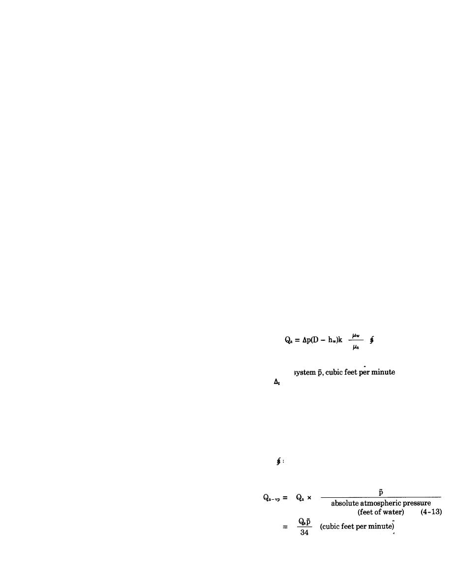
The required capacity of the vacuum pump can be esti-
should be expected but is difficult to estimate. As an
mated from formulas for the flow of air through por-
approximation, the seepage through a steel sheet pile
ous media considering the maximum exposure of the
wall should be assumed equal to at least 0.01 gallon
tunnel facing or shaft wall at any one time to be the
per square foot of wall per foot of net head acting on
most pervious formation encountered, assuming the
the wall. The efficiency of a sheet pile cutoff is sub-
porous stratum to be fully drained. The flow of air
stantial for short paths of seepage but is small or negli-
through a porous medium, assuming an ideal gas flow-
gible for long paths.
ing under isothermal conditions, is given in the follow-
(b) Sheet pile cutoffs that are installed for long-
ing formula:
term operation will usually tighten up with time as the
interlocks become clogged with rust and possible in-
(4-12)
crustation by the groundwater.
(4) Freezing. Freezing the water in saturated por-
where
ous soils or rock to form an ice cutoff to the flow of
Qa = flow of air at mean pressure of air in flow
groundwater may be applicable to control of ground-
water for shafts or tunnels where the excavation is
pressure differential p1-p2) in feet of water
P=
small but deep. (See para 4-12 for information on de-
absolute atmospheric pressure
p1 =
sign and operation of freezing systems.)
absolute air pressure at line of vacuum wells
p2 =
D=
thickness of aquifer, feet
4-10. Dewatering shafts and tunnels.
hW =
head at well, feet
a. The requirements and design of systems for de-
coefficient of permeability for water, feet per
k=
watering shafts and tunnels in cohesionless, porous
minute
soil or rock are similar to those previously described
w =
absolute viscosity of water
for open excavations. As an excavation for a shaft or
absolute viscosity of air
a =
tunnel is generally deep, and access is limited, deep-
=
geometric seepage shape factor (para 4-3)
wells or jet-eductor wellpoints are considered the best
The approximate required capacity of vacuum pump is
method for dewatering excavations for such structures
expressed as
where dewatering techniques can be used. Grout cur-
tains, slurry cutoff walls, and freezing may also be
used to control groundwater adjacent to shafts or tun-
nels.
b. Where the soil or rock formation is reasonably
homogeneous and isotropic, a well or jet-eductor sys-
4-47


 Previous Page
