CEMP-E
TI 809-07
NOVEMBER 1998
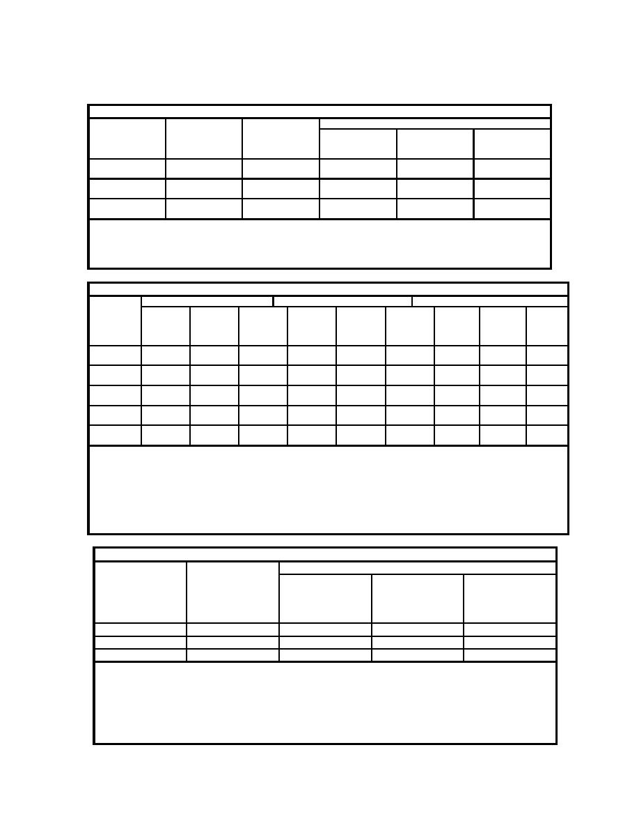
Table 2-7: Suggested Capacity for Powder Driven Fasteners in Concrete
Shank Diameter
Minimum
Type of Loading
Concrete Compressive Strength MPa (psi)
Penetration
13.8 (2000)
20.7 (3000)
27.6 (4000)
Mm (in)
mm (in)
N (lbs)
N (lbs)
N (lbs)
3.68
29
Pullout
0.40 (90)
0.51 (115)
0.65 (145)
(0.145)
(1-1/8)
Shear
0.71 (160)
1.00 (225)
1.18 (265)
4.50
37
Pullout
0.67 (150)
0.91 (205)
1.22 (275)
(0.177)
(1-7/16)
Shear
1.11 (250)
1.27 (285)
1.47 (330)
5.21
32
Pullout
0.98 (220)
1.25 (280)
1.54 (345)
(0.205)
(1-1/4)
Shear
1.74 (390)
1.98 (445)
2.22 (500)
Notes:
1. Capacities shown are for stone aggregate concrete and are based on a low velocity shot.
2. Minimum fastener spacing: 4"; minimum fastener edge distance: 3".
3. Values may not be increased by 1/3 for wind or seismic loads.
4. ICBO uninspected values - Hilti/ICBO research #2388.
Table 2-8: Suggested Capacity for Powder Driven Fasteners in Structural Steel
Steel
Shank Dia: 3.68 mm (0.145")
Shank Dia: 4.50 mm (0.177")
Shank Dia: 5.21 mm (0.205")
Thickness
!3 mm
9.53 mm
6.35 mm
13 mm
9.53 mm
6.35 mm
13 mm
9.53 mm
6.35 mm
(")
(3/8")
(")
(")
(3/8")
(")
(")
(3/8")
(")
kN(lbs)
kN(lbs)
kN(lbs)
kN(lbs)
kN(lbs)
kN(lbs)
kN(lbs)
kN(lbs)
kN (lbs)
mm (in)
2.583
0.93
0.93
0.93
1.49
1.76
1.76
2.16
2.34
2.94
(0.1017)
(210)
(210)
(210)
(335)
(395)
(395)
(485)
(525)
(660)
1.811
0.93
0.93
0.93
1.49
1.76
1.76
2.16
2.34
2.58
(0.0713)
(210)
(210)
(210)
(335)
(395)
(395)
(485)
(525)
(581)
1.438
0.93
0.93
0.93
1.49
1.76
1.76
2.16
2.07
2.07
(0.0566)
(210)
(210)
(210)
(335)
(395)
(395)
(485)
(465)
(465)
1.146
0.93
0.93
0.93
1.43
1.43
1.43
1.65
1.65
1.65
(0.0451)
(210)
(210)
(210)
(321)
(321)
(321)
(372)
(372)
(372)
0.879
0.88
0.88
0.88
1.10
1.07
1.07
1.24
1.24
1.24
(0.0346)
(197)
(197)
(197)
(247)
(241)
(241)
(279)
(279)
(279)
Notes:
1. Tests were conducted with the fastener point driven completely through the back side of the hot-rolled steel member. This
was necessary to obtain proper gripping force.
2. Fasteners should not be located less than 13 mm (1/2") from the edge of steel.
3. A minimum fastener spacing of 38 mm (1-1/2") is necessary.
4. Bearing strength based upon: 1.15(228 MPa)(Bearing Area) [1.15(33ksi)(Bearing Area)] for cold-formed steel.
5. Capacities shown are for either shear or pullout.
6. Values may not be increased by 1/3 for wind or seismic loads.
7. ICBO uninspected values - Hilti/ICBO research #2388
Table 2-9: Joist End Clip: Allowable Loads per fastener
Clip Length
No. of screws in
Joist Thickness
Each Leg
0.8879 mm
1.146 mm
1.438 mm
(0.0346")
(0.0451")
(0.0586")
228 MPa (33 ksi) 228 MPa (33 ksi) 228 MPa (33 ksi)
mm (in)
(#10-16)
kN (lbs)
kN (lbs)
kN (lbs)
152 (6)
3
1.50 (337)
2.23(501)
4.76 (1070)
203 (8)
4
2.14 (480)
3.17 (713)
6.77 (1523)
254 (10)
5
2.78 (626)
4.14 (930)
8.83 (1985)
Notes:
1. Based on CCFSS technical bulletin vol. 2, no. 1 which outlines the proposed AISI specification
provisions for screw connections.
2. F = 228 MPa (33 ksi) for 0.879 mm (0.0346") sheets. F = 345 MPa (50 ksi) for 1.438 mm
y
y
(0.0566") sheets. F = 1.08F
u
y
3. Allowable loads based on a factor of safety of 3.0.
2-14


 Previous Page
