CEMP-E
TI 809-07
30 November 1998
Acceptance Criteria: Acceptance criteria for each performance objective are prescribed for each
analytical procedure in Chapter 6 and numerical values for each of the criteria are given in
Chapters 7 through 10.
3. STRUCTURAL DESIGN CRITERIA. The basic lateral and vertical seismic-force-resisting systems
considered here are diagonal strap configurations (Panels A1, A2, and D1) in Appendix B. These are
considered bearing wall systems. The format of Table 5.2.2 of FEMA 302 is used in Table 3-1 to present
the response modification coefficient, R and deflection amplification factor, Cd. These values are used to
calculate the base shear, and design story drift. The system overstrength factor, Ω0 used in FEMA 302 is
not included here because shear panel overstrength is accounted for by Ω0QE in Equation C-16. This is
the maximum lateral capacity of the shear panel based on the maximum estimated ultimate stress of the
panel diagonal straps.
The response modification coefficient, R in the direction under consideration at any story shall not exceed
the lowest value for the seismic-force-resisting system in the same direction considered above that story
excluding penthouses. Other structural systems (dual systems) may be used in combination with these
cold-formed steel panels, but then the smallest R value for all systems in the direction under
consideration must be used for determining the loads applied to the entire structure in that direction. Dual
systems must be used with caution, particularly if differences in stiffness result in interaction effects
(FEMA 302, 5.2.2.4.2) or deformation compatibility problems (FEMA 302, 5.2.2.4.2). Another structural
system may be used in the orthogonal direction with different R values, and the lowest R value for that
direction only shall be used in determining loads in that orthogonal direction.
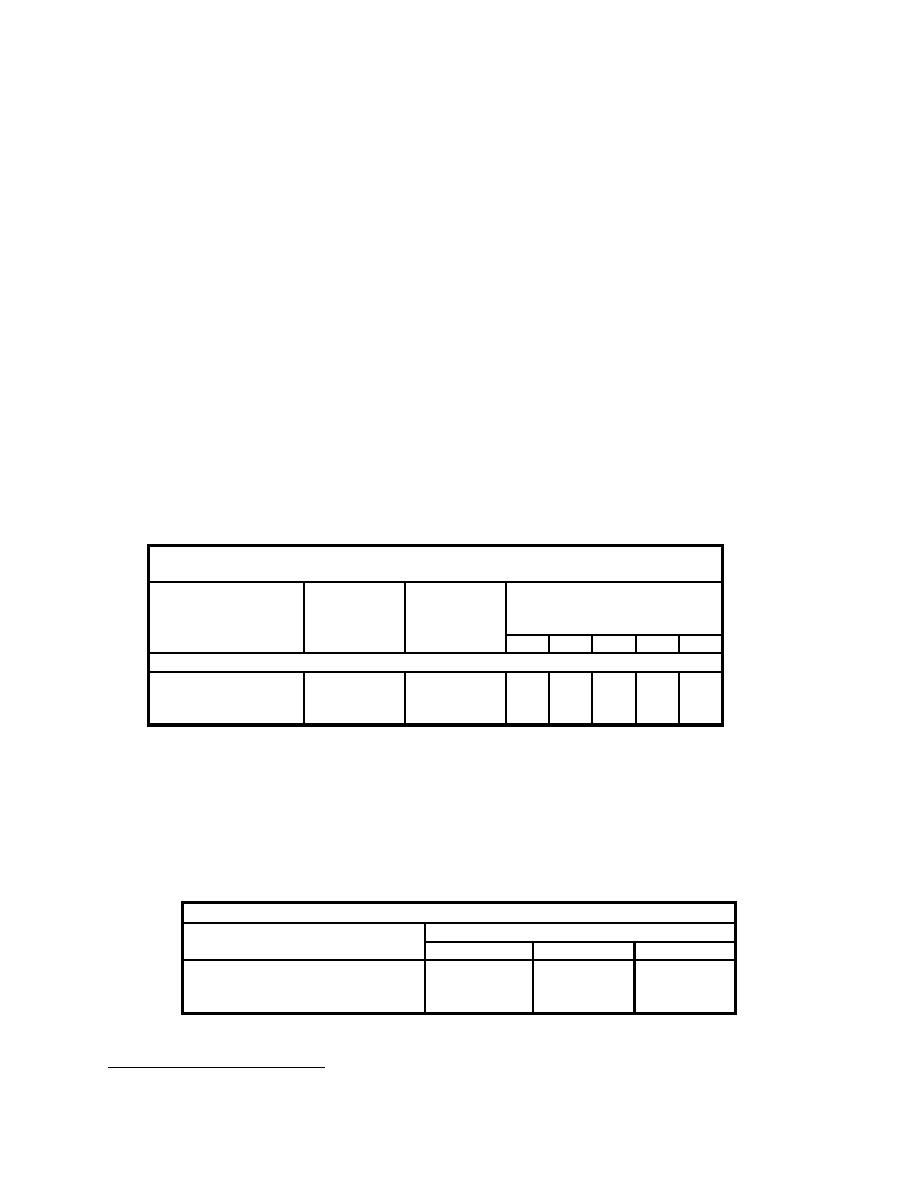
Table 3-1 Design Coefficients and Factors for Basic Seismic-Force-Resisting
Systems
Deflection
Basic Seismic-
Response
System Limitations and
Modification Amplification Building Height Limitations (ft)
Force-Resisting
Factor, Cd
System
Coefficient,
by Seismic Design Category
R
B
C
D
E
F
Bearing Wall Systems
Cold-Formed Steel
Shear Panels with
4
3
NL
NL
65
65
65
Diagonal Strapping
4. DEFLECTION AND DRIFT LIMITS. The design story drift, ∆ shall not exceed the allowable story
drift, ∆a as obtained from Table 3-2 (FEMA 302, Table 5.2.8), for any story. The design story drift shall be
computed as the difference of deflections at the center of mass at the top and bottom of the story under
consideration, as determined by Equation C-29 (FEMA 302, Eq 5.3.7.1). For structures with significant
torsional deflections, the maximum drift shall include torsional effects. All portions of the structure shall
be designed and constructed to act as an integral unit in resisting seismic forces unless separated
structurally by a distance sufficient to avoid damaging contact under total deflection, δx, as determined by
Equation C-29, (FEMA 302, 5.2.8).
Table 3-2 Allowable Story Drift, ∆a (mm or inches)
Structure
Seismic Use Group
I
II
III
Structures with diagonal strap
0.020hsx1
shear walls
0.015hsx
0.010hsx
1
hsx is the story height below level x.
3-3


 Previous Page
