
CEMP-E
TI 809-07
30 November 1998
5. TORSION. The distribution of lateral seismic forces shall take into account the effects of torsional
moment, Mt resulting from the location of masses relative to the center of rigidity (stiffness) of the lateral
force resisting frames in both orthogonal directions (FEMA 302, 5.3.5). This torsional moment shall
include the effects of accidental torsional moment, Mta caused by an assumed offset of the mass. This
offset shall be equal to 5 percent of the dimension of the structure orthogonal to the direction of the
applied seismic force. Similar to the lateral seismic forces, the torsional moments, Mt are distributed
along the floors of the building according to the vertical distribution factor given in Equation C-26.
The torsional resistance comes from each of the shear wall panels, and the resistance from each panel is
proportional to the square of the distance from the center of resistance to the plane of the panel. For a
given panel the additional shear force due to torsion, Qsi can be expressed as:
Q si = k si ∆ i = k siρi θ
(Eq 3-1)
Where:
ksi = the shear stiffness of shear panel i, and is defined as follows:
W
k si = En sb s t s 2
(Eq 3-2)
H + W
2
∆i = the lateral in-plane shear deflection of panel i.
ρi = the distance from the center of resistance to panel i, perpendicular to the plane of the panel.
θ = the torsional rotation of the building at the floor level above the panel.
E = the modulus of elasticity of steel, equal to 200,000 MPa (29,000 ksi).
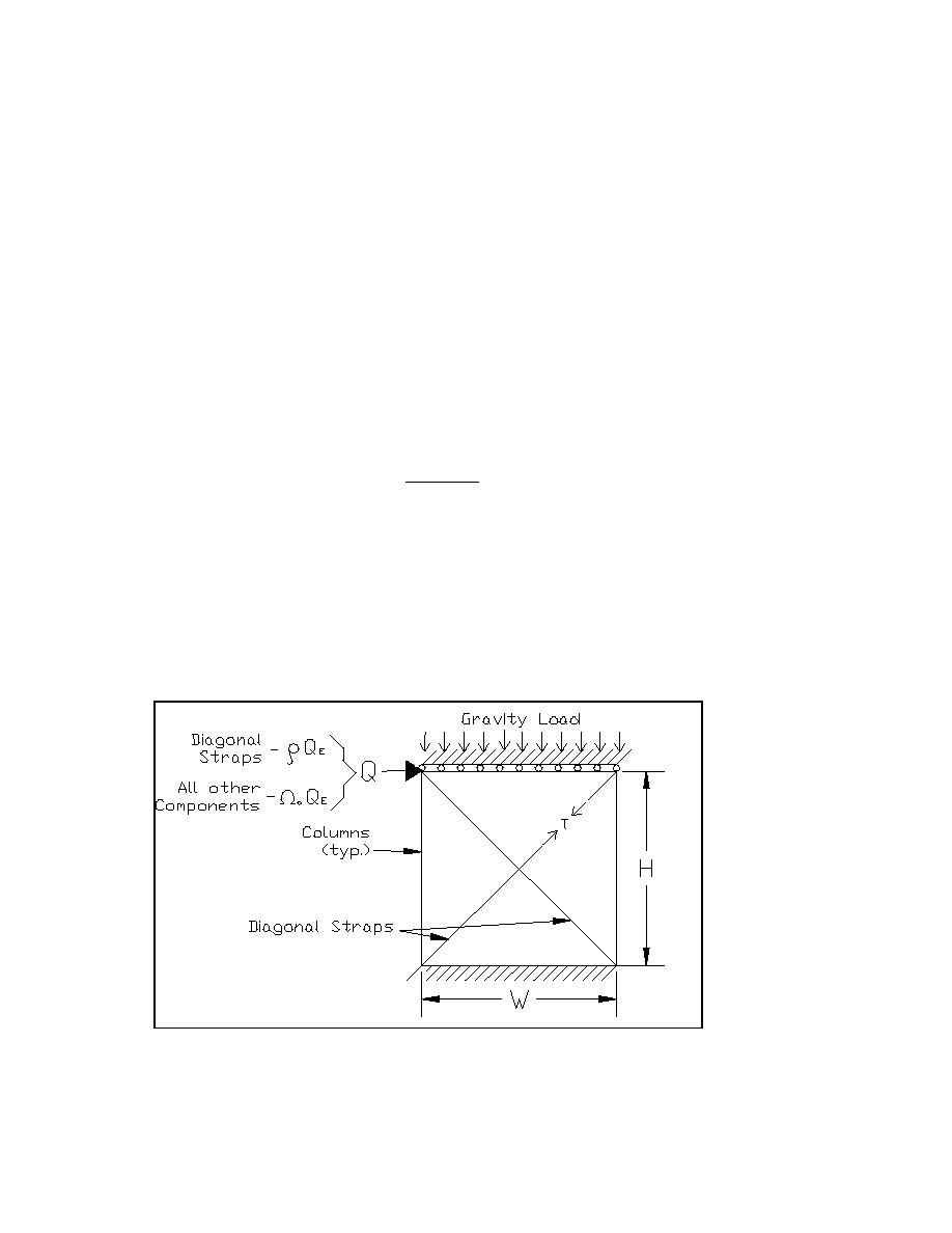
ns = the number of diagonal straps.
bs = the width of the diagonal straps.
ts= the thickness of the diagonal straps.
W = the overall panel width.
H = the overall panel height (see Figure 3-2 for a schematic panel drawing showing W and H).
Figure 3-2. Schematic of CERL cold-formed steel shear panel model.
The torsional moment resistance, Mtr, for all the shear panels is given by:
3-4

 Previous Page
