TM 5-809-3/NAVFAC DM-2.9/AFM 88-3, Chap. 3
7-5 provide a graphical solution for equations 7-13 (for fixed ended rectangular piers) and 7-14 (for
cantilever rectangular piers), respectively. When walls of different moduli of elasticity, Em, are being
compared, the deflection values shall be multiplied by the ratio of 1.35 x 10⁶/Em. When walls of different
actual thicknesses or equivalent thicknesses, t, are being compared, the deflection values shall be multiplied
by the ratio of 12/t. In corner pier curves (1 and 3) the corner pier moment of inertia, I, is assumed to be 1.5
times that of the rectangular pier. The equations for the corner piers are derived by the procedure given above
(using equation 7-8 and 7-9) except that (1.5)I is substituted for I in the bending term of the equations, and
the correction factor of 1.2 in the shear term of the equations is replaced by 1.0, since the section can no
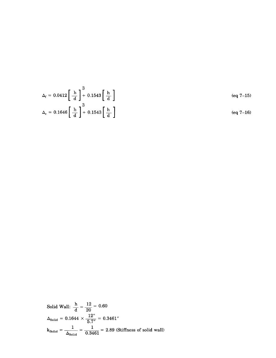
longer be considered rectangular. These substitutions result in equations 7-15 (for a fixed ended corner pier)
and equation 7-16 (for a cantilever corner pier) as follows:
For other values of I, the flexural portion of the deflection curves would be proportional. The deflections
shown on the charts are reasonably accurate. The formulas written on the curves can be used to check the
results. However, the charts will give no better results than the assumptions made in the shear wall analysis.
For instance, the point of contraflexure of a vertical pier may not be in the center of the pier height. In some
cases the point of contraflexure may be selected by judgment and an interpolation made between the
cantilever and fixed conditions.
7-9. Design examples. The following design examples illustrate the procedure for determining the rigidity
of a shear wall section with one opening and give the complete design of a shear wall with two openings.
a. Design example 1.
(1) Given:
(a) 12-inch normal weight CMU
(b) Wall height (h) = 12 feet
(c) Wall length (d) = 20 feet
(d) Reinforcement = #5 bars @ 24" o.c.
(e) Type S mortar is used with:
f'm = 1350 psi
Em = l000f'm = 1,350,000 psi
Ev = 0.4Em = 540,000 psi.
(f) There is a 4-feet by 4-feet window opening centered in wall.
(2) Problem. Determine the rigidity of the wall.
(3) Solution. The procedure involves determining the rigidities or stiffnesses of each segment within
the shear wall element. The method is based on the deflection charts of figure 7-5. In this method; the
deflection of the solid wall is determined, the deflection of the horizontal strip of the wall containing all the
openings is deducted from the solid wall deflection, and then the deflections of the piers within this opening
strip are added to this modified wall deflection to obtain the total deflection of the actual wall with openings.
The reciprocal of this deflection value becomes the relative rigidity of that wall. Note that the following
solution is carried out, in some instances, to four significant figures. This was done for calculation purposes
and does not imply that the deflections would actually be accurate to the degree of precision since the
procedure used is only approximate with simplified assumptions made.
(a) A solid wall containing ABCD with no openings is assumed fixed at the bottom only (use
rectangular pier cantilever curve #4 from figure 7-5). Note that the equivalent wall thickness for 12-inch
CMU with grouted cells @ 24" o.c. from table 5-2 is 5.7 inches.
7-8


 Previous Page
