TM 5-809-3/NAVFAC DM-2.9/AFM 88-3, Chap. 3
A3 = [bt + (n - 1)As]
b = The actual width of the column or pilaster, inches.
t = The least actual thickness of the column or pilaster, inches.
n = Modular ratio.
= Es/Em
Es = 29,000,000 psi.
Em = 1000f'm for CMU.
f'm = The compressive strength of masonry, psi.
As = The cross-sectional area of reinforcing steel, in2.
b. Allowable axial compressive stress. The allowable axial compressive stress for masonry columns and
pilasters, Fa, is as follows:
Fa = [0.l8f'm + 0.65(pg)(Fsc)][R] (psi)
(eq 9-2)
Where:
pg = The ratio of the cross-sectional area of the reinforcement to the gross area of the masonry
section based on actual dimensions.
pg = As/Ag
Ag = The gross area of masonry section based on actual dimensions, in2.
Fsc = Allowable compressive stress in steel, psi.
= 0.4fy
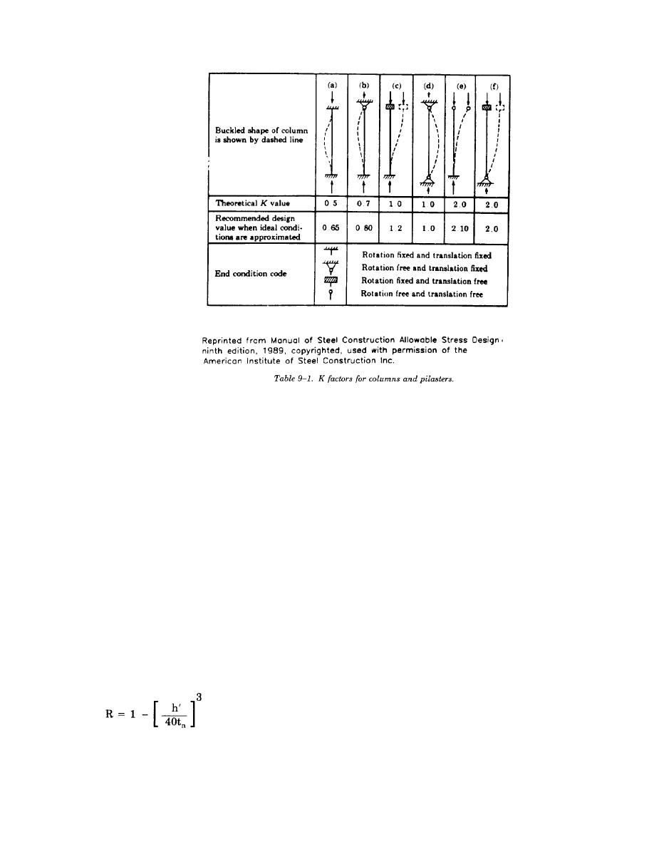
R = The stress reduction factor
tn = Least nominal thickness of column or pilaster, inches.
Note. Fa may be increased by a factor of 1.33 when wind or seismic loads are considered.
In equation 9-2, the "0.l8f'm" is the allowable axial compressive stress provided by the masonry and the
"0.65pgFsc" is the allowable compressive stress added to the section by the vertical reinforcement. The third
9-6


 Previous Page
