TM 5-809-3/NAVFAC DM-2.9/AFM 88-3, Chap. 3
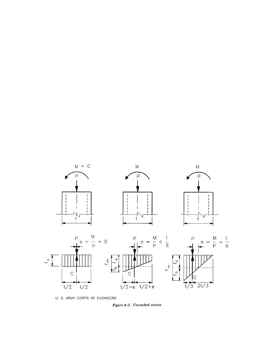
compressive stress is greater than the bending tensile stress; the entire cross section remains in compression
and the section properties will be based upon what is termed the "uncracked section". This condition occurs
when the virtual eccentricity, ev, is less than or equal to 1/6 of the thickness, t, of the member. ev is defined
as the ratio of the moment, M, to the axial load, P. Figure 9-3 shows the uncracked section with three loading
conditions where ev is less than or equal to t/6. When the flexural tensile stresses exceed the axial
compressive stresses (ev exceeds t/6) and the edge of the compressive stress block is at or outside the location
of the reinforcing steel, the stress distribution is as shown in figure 9-4a. This condition, where the section
is cracked but the reinforcing steel is not in tension, is not a consideration when the unity equation (equation
9-8) is used for design of combined stresses. It is, however, a point used in the development of the interaction
diagram for a masonry pilaster or column. When the flexural tensile stresses exceed the axial compressive
stresses, a portion of the cross section is cracked and the design cross sectional properties are based upon
a reinforced masonry "cracked section" as shown in figure 9-4(b). Since it is assumed that the masonry will
not resist tension, the reinforcement must resist all tensile forces. The design will be governed by the
compressive stresses (axial and flexural) developed within the masonry section or by the flexural tensile
stresses developed in the reinforcement. The combined loading effects will be considered in the design by
using the basic unity interaction equation given later in this chapter.
d. Reaction location. Special consideration will be given to the effects created by the type and connection
conditions of the members (beams, girders, trusses, etc.) supported by the masonry column or pilaster. If
these members are not restrained against rotation, the resulting reaction will tend to move toward the edge
of the support, increasing the eccentricity of the reaction. When a beam supported on a bearing plate is
subject to rotation under loading, the vertical resultant reaction will be assumed at the third point of the
bearing plate, as shown in figure 9-5(a). When a supported member displays very little rotation, due to its
stiffness or continuity with other supported members, the load will be more uniformly distributed over the
length of the plate, and the resulting reaction may be assumed to act at the center of the bearing plate, as
shown in figure 9-5(b).
9-3


 Previous Page
