TM 5-809-3/NAVFAC DM-2.9/AFM 88-3, Chap. 3
term, R, reduced the stress to the point where buckling will not occur. R also accounts for the increase in
moment due to lateral deflection or the P-Delta effect.
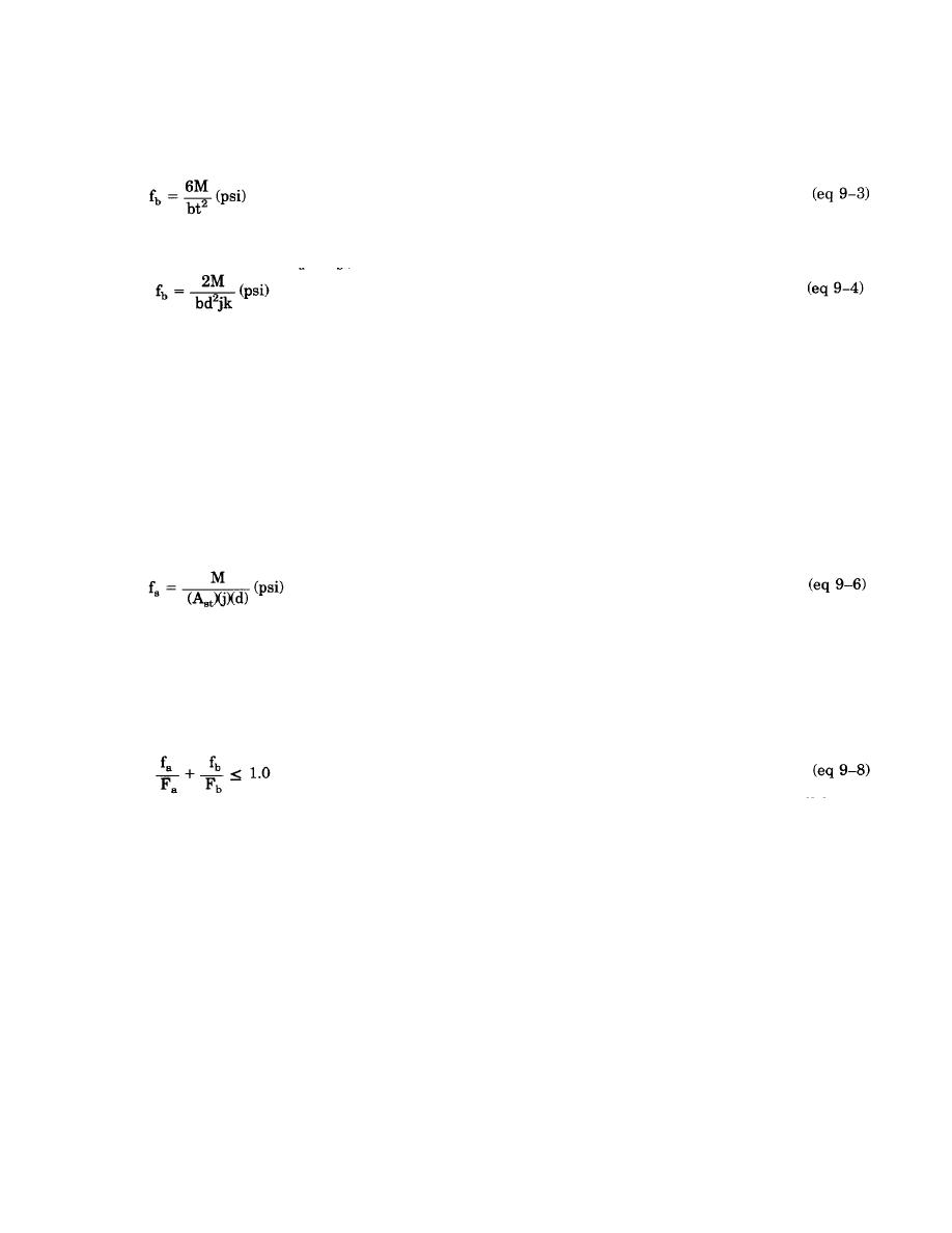
c. Flexural compressive stress. The computed flexural compressive stress, fb, is computed as follows:
For an uncracked section (fa $ fb);
Where:
M = The computed bending moment, inch-lbs.
For a cracked section (Fa < fb );
Where:
d = The effective depth of the flexural section measured from the extreme compression fiber to the
centroid of the tension reinforcement, inches.
k = The ratio of the depth of the compressive stress to the depth, d.
j = The ratio of the distance between the centroid of the flexural compressive forces and the centroid
of the tensile forces to the depth, d.
j = 1 - k/3.
d. Allowable flexural compressive stress. The allowable flexural compressive stress for masonry columns
and pilasters, Fb, is determined as follows:
Fb = 0.33f*m (psi)
(eq 9-5)
If f*m = 1,350 psi; Then Fb = 0.33(1,350) = 450 psi
Note. Fb may be increased by a factor of 1.33 when wind or seismic loads are considered.
e. Flexural tensile stress. When tension reinforcing is required, the steel tensile stress, fs, will be
determined as follows:
Where:
Ast = The cross sectional area of the reinforcing steel that is considered in tension only, psi.
f. Allowable flexural tensile stress. The allowable tensile stress in reinforcing steel, Fs, when the yield
strength of the reinforcement is equal to or greater than 60,000 psi is:
Fs =24,0000(psi)
(eq 9-7)
Note. Fs may be increased by a factor of 1.33 when wind or seismic loads are considered.
g. Combined loading. Members subjected to combined axial and flexural stresses will be designed by the
basic interaction equation as follows:
Note. When Fa and Fb are increased by 1.33 for wind or seismic loads, the resulting design will be not less
than the design determined using dead and live loads only. Load interaction methods based on accepted
principles of mechanics may be used in lieu of equation 9-8.
h. Design considerations. The design of masonry columns or pilasters will consider the maximum loading
conditions at the top of the member; at (or near) mid-height of the member, where the maximum bending will
usually occur; and at the bottom of the member. Normally, masonry columns or pilasters will be given lateral
support at the top by roof or floor system members and will be connected to the foundation below with
reinforcing dowel bars. For this condition, the conservative assumption is made that the tops and bottoms
of the members are simple supports. When other support or fixity conditions exist, calculations will be based
on established principles of mechanics. At the top of a column or pilaster, a combination of the axial load,
P, the eccentric moment, Pe, and any other loads and moments present will be considered. When determining
Fa at the top of the member, the load reduction factor need not be considered. At (or near) the mid-height
of a column or pilaster, a combination of axial load, P, the eccentric moment, approximately Pe/2, the lateral
load moment, and any other loads and moments present will be considered. At mid-height, the P-Delta effect
is at its maximum, thus Fa will be reduced by the load reduction factor, R. Since some value of lateral loads
and lateral load moments will generally act in either direction on the member, the maximum combination of
axial load, eccentric moment at the mid-height, moments created by lateral loads acting in either direction
will be considered.
9-7


 Previous Page
