TM 5-809-3/NAVFAC DM-2.9/AFM 88-3, Chap. 3
CHAPTER 9
COLUMNS AND PILASTERS
9-1. Introduction. This chapter covers the design of reinforced masonry columns and pilasters. These
structural elements are defined by their sectional configurations and heights. A masonry column is a vertical
compression member whose height exceeds three times its thickness and whose width is less than one and
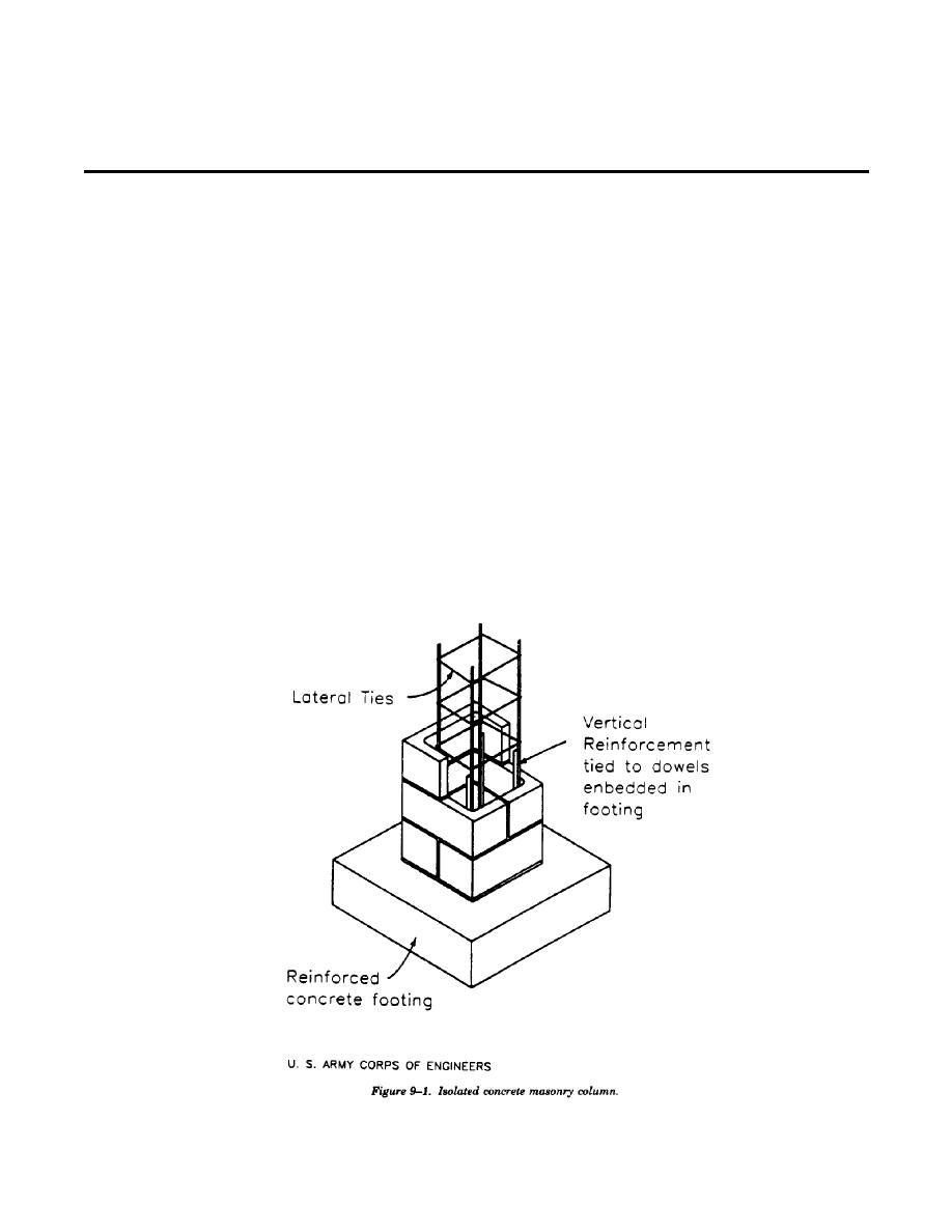
one-half times its thickness. Figure 9-1 shows an isolated CMU column supported by a spread footing. A
masonry pilaster is a vertical member of uniform cross section built as an integral part of a wall which may
serve as either a vertical beam or a column or both. A pilaster projects from one or both faces of an
unreinforced wall and usually projects in a reinforced wall. Figure 9-2 shows details of a typical reinforced
CMU pilaster. Pilasters are designed similar to columns except that pilasters are laterally supported in the
direction of the wall, while columns are typically unsupported in both directions. General design criteria,
section properties, and allowable stresses used but not contained herein are covered in chapter 5.
9-2. Minimum requirements.
a. Limiting dimensions. The least nominal dimension of a masonry column or pilaster will be 12 inches,
except that 8 inches minimum may be used provided the axial stress is not more than one-half the allowable
axial stress.
b. Vertical reinforcement. The vertical reinforcement will not be less than 0.005Ag nor more than 0.04Ag,
where Ag is the gross area of the column or pilaster in square inches. A minimum of four No. 4 bars will be
used. Bar lap splice lengths will be sufficient to transfer the design loads in the reinforcement, but not less
than 48 bar diameters.
c. Lateral ties. All longitudinal bars for columns or pilasters will be enclosed by lateral ties. The minimum
lateral tie size will be #2 bars for #7 or smaller vertical reinforcement and #3 bars for larger vertical
reinforcement. The ties will be spaced not more than 16 bar diameters, 48 tie diameters, or the least nominal
9-1


 Previous Page
