TM 5-809-3/NAVFAC DM-2.9/AFM 88-3, Chap. 3
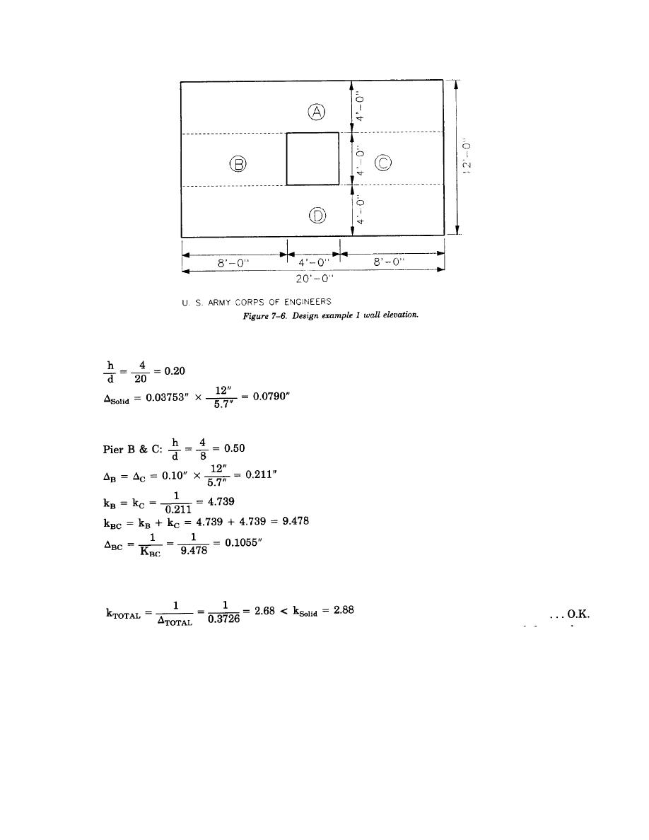
(b) The deflection of the solid middle 4*-0" strip containing B and C is determined assuming it is
a fixed pier (use rectangular pier fixed curve #2 from figure 7-5) as follows:
(c) The individual deflections of piers B and C are determined assuming fixed top and bottom (use
rectangular pier fixed curve #2 from figure 7-5) as follows:
(d) The total shear wall deflection and stiffness can now be found as follows:
)TOTAL = )Solid = )Strip = )BC
)TOTAL = 0.3461" - 0.0790" + 0.1055" = 0.3726"
(4) Summary. The design example solution provided above illustrates the recommended procedure for
determining the relative rigidity of a masonry shear wall element. Note that the relative rigidity of this wall
element with one opening is about 93% of the solid wall element rigidity. Thus, it can be concluded that the
opening has not significantly reduced the rigidity of the shear wall.
b. Design example 2.
(1) Given:
(a) 8-inch normal weight CMU
(b) Wall height (h) = 12 feet
(c) Wall length (d) = 20 feet
(d) In-plane shear force from wind loading (V) = 10 kips
(e) Axial loads (Concentrically applied):
Dead load = 300 pounds per foot
Live load = 600 pounds per foot
7-11


 Previous Page
