TM 5-809-3/NAVFAC DM-2.9/AFM 88-3, Chap. 3
(f) Reinforcement:
#5 bars @ 24" o.c.
fy = 60,000 psi
Es = 29,000,000 psi
(g) Modular ratio (n) = Es/Em = 21.5
(h) Equivalent wall thickness = 4.1 inches (table 5-2).
(i) Type S mortar is used with:
f*m = 1350 psi
Em = l000f'm 1,350,000 psi
Ev = 0.4Em = 540,000 psi.
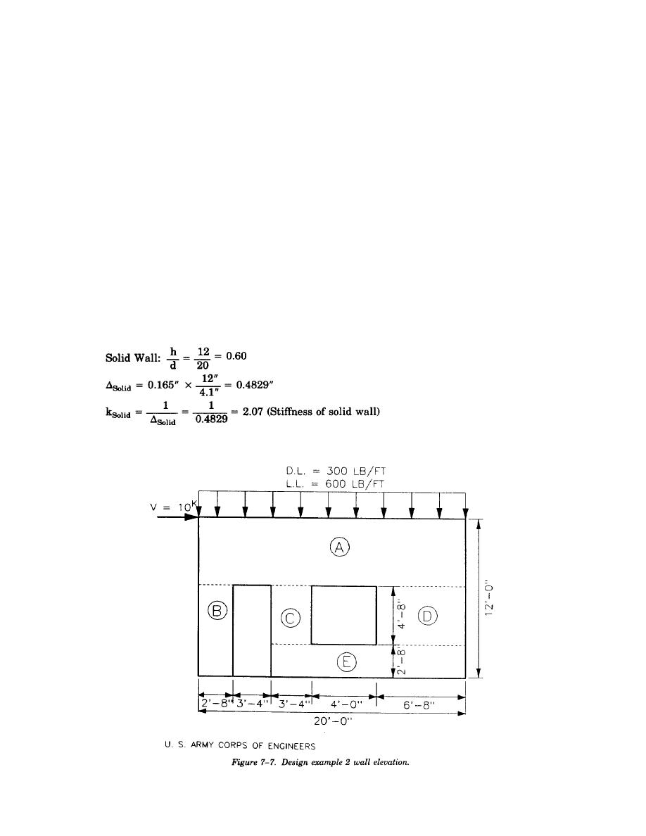
(j) There is a door and a window opening as shown in figure 7-7.
(2) Problem. Design the given shear wall to withstand the shear and axial forces applied.
(3) Solution. The design procedure involves determining the rigidities of each segment (pier) within the
shear wall. The method used is based on the deflection charts of figure 7-5. The horizontal loading is then
proportioned to each segment based on its rigidity relative to the other segments, with longer and shorter
segments receiving the greater load. Each wall segment will then be analyzed by checking the flexural, axial,
and shear stresses.
(a) The first step in designing the shear wall is to determine the relative rigidities or stiffnesses of
the shear wall segments. The method used in determining the relative rigidities is similar to the procedure
followed in design example 1.
A solid wall containing ABCDE with no openings is assumed fixed at the bottom only. The deflection and
rigidity are determined (use rectangular pier cantilever curve #4 from figure 7-5) as follows:
The deflection of the solid bottom strip, 7.33 feet high, containing BCDE is determined (use rectangular pier
cantilever curve #4 from figure 7-5) as follows:
7-12


 Previous Page
