TM 5-809-3/NAVFAC DM-2.9/AFM 88-3, Chap. 3
SPe
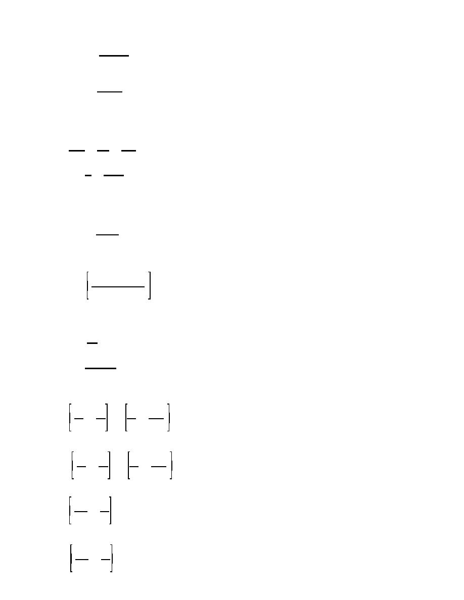
Mmax '
(lb&ft/S)
(eq 6-6)
(12)(12)
(2) When w > 0 and P is not eccentric, the maximum moment occurs at mid-height of the wall where x =
h/2 and equation 6-5 2becomes:
Swh
Mmax '
(lb&ft/S)
(eq 6-7)
(12)(8)
(3) When w > 0, P is eccentric, and the moments due to "w" and "Pe" are additive; the location of the
maximum moment can be determined by differentiating the moment equation with respect to x, setting the
equation equal to zero, and then solving for x. By performing this operation on equation 6-3, the "x" location
where the maximum moment occurs can be determined as follows--
dMx
wh
Pe
'
%
& wx '0
dx
2
12h
Solving for x;
h
Pe
x'
%
(ft)
(eq 6-8)
2
12wh
It should be reiterated that this maximum moment condition will occur only when the moment due to the
eccentricity of the axial loads and the moment due to the lateral load are additive. Substituting equation 6-8
into 6-2, the maximum moment, per length of wall equal to reinforcing bar spacing, 5, can be found as
follows:
S(Ra)2
Mmax '
(ft&lbs/S)
(eq 6-9)
2w
Equations similar to 6-3 through 6-9 can be similarly derived for the case when the moment due to lateral
loading and the moment due to eccentric axial loading are not additive.
b. Axial compression equations. The axial stress at any height, h, in a wall is determined as follows:
P % w2(h & x)
fa '
(psi)
(eq 6-10)
Ae
Where:
w2 = The weight of the wall, psf.
Ae = The effective area of the wall, in2/ft.
(1) When x = h (top of wall), there is no wall weight and equation 6-10 becomes:
P
fa '
(psi)
(eq 6-11)
Ae
(2) When x = 0 (bottom of wall) the entire wall weight is included and equation 6-10 becomes:
P % w2h
fa '
(psi)
(eq 6-12)
Ae
c. Combined stresses.
(1) In walls subject to combined axial compression and flexural stresses, the masonry will be designed
in accordance with the interaction equations as follows--
fa
fb
fa
Mx
# 1.00
%
%
OR
(eq 6-13)
Fa
Fb
Fa
Mrm
Since a 33% overstress is allowed when wind or seismic loads are considered, the allowable stresses and
resisting moment in equation 6-13 may be increased by 33% or interaction equation 6-14 may be used.
fa
fb
fa
Mx
# 1.33
%
%
OR
(eq 6-14)
Fa
Fb
Fa
Mrm
(2) In walls subject to combined axial and flexural stress, the reinforcing steel will be designed using
interaction equations as follows:
Mx
fa
# 1.00
&
(eq 6-15)
Mrs
Fa
Since a 33% overstress is allowed when wind or seismic loads are considered, the allowable stress and
resisting moment in equation 6-15 may be increased by 33% or interaction equation 6-16 may be used.
Mx
fa
# 1.33
&
(eq 6-16)
Mrs
Fa
6-3


 Previous Page
