The resulting stress ratio on the left side is;
105.31ft - kips (12"/1' ) / 35.3 - in3
M toe / S x,toe
σ toe- of - haunch
=
=
= 1.6 > 1.2
O.K.
108.35ft - kips (12"/1' ) / 58 - in3
σ face- of - column M face / S x,haunch
Strength requirements;
Roof Beam:
The following maximum loads were obtained from the analysis output at the toe of the haunch;
M u,beam = 23.06ft - kips (31.3KN - m), Vu,beam = 6.37 k (28.33KN)
φb M n = 109 ft - kips (147.8KN-m) per AISC LRFD 2nd ed. load factor design selection table (using an
unbraced length ` b'of the compression flange of 5'
L
)
k
nd
φv Vn = 69 (306.9KN)
per AISC LRFD 2 ed. maximum uniform load tables
∴ M u,beam = 23.06ft - kips < 109 ft - kips = φb M n (31.3KN-m < 147.8KN-m)
O.K.
Vu,beam = 6.37 k < 69 k = φv Vn (28.33KN < 306.9KN)
O.K.
Check unbraced length of beam flanges (per AISC seismic provisions);
Try 5'on center (same spacing as the perpendicular floor joists);
2500(1.08" )(1'/12" ) 2500ry
L b = 5' < 6.25' =
=
O.K.
(1.53m < 1.91m)
36ksi
Fy
Therefore provide lateral support to beam flanges at 5-ft (1.53m) o.c.
Column:
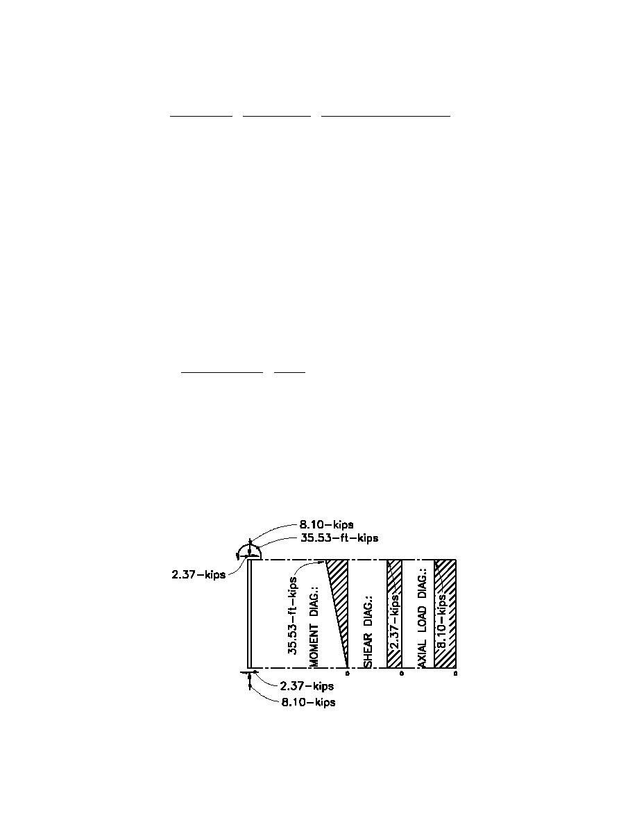
Columns are loaded both in flexure and axially and are therefore beam columns. Additionally, the frames
the columns are in are not braced against sidesway and therefore magnified moments due to sidesway must
be determined.
A free body diagram showing loading as well as moment, shear, and axial load diagrams for the most
highly loaded column are shown below.
1-kip = 4.448KN
1-ft-kip = 1.36KN
H4-26


 Previous Page
