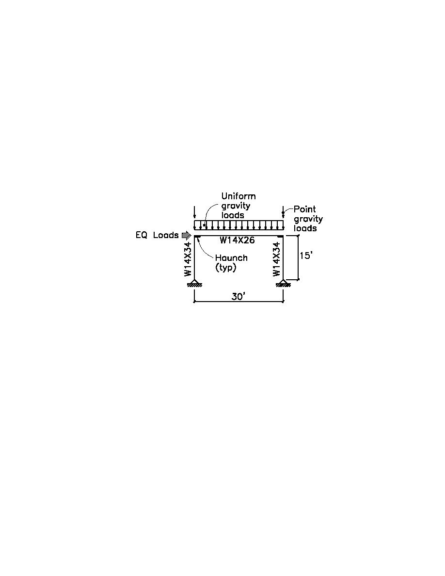
(5) Moment Frames (Low Roof).
There will be one design for the worst case situation and this design will be used throughout the low roof.
The worst case situation is the interior moment frame because it supports the largest tributary area.
Determine Design Loads:
wL:
Live load reduction per ANSI/ASCE 7-95;
AT = 20' 30' = 600-ft2 (55.7m2) ⇒ R1 = 0.6
( )
Roof slope is flat ∴ R2 = 1.0
∴ wL = 20' 20psf)0.6 = 240plf (3.50KN/m)
(
wD = 20' 17.1psf)
(
= 342plf (4.99KN/m)
PD = 5.9psf(7.5' (20' = 885-lb (3.94KN) (point load due to wt. of side walls)
)
)
E = 1.0QE = 0.95 (4.23KN) (applied as a uniform load of 0.95k/30'= 31.7plf (0.46KN/m) along the
k
beam length)
1-in = 25.4mm
1-ft = 0.30m
1-lb = 4.448N
Design Members:
Note; Haunch properties Ix, Iy, Sx, and A as well as the length of the haunch were previously calculated as;
Ix = 640-in4 (266.4X106 mm4), Iy = 13.3-in4 (5.54X106 mm4), Sx = 58-in3 (950.4X103 mm3), A = 11.48-
in2 (7.41X103 mm2), and ` ' length from centerline of column to toe of haunch is 1.85' (22.25-in or
L
0.56m).
General;
The moment frame was analyzed using a two-dimensional computer analysis program (RISA-2D, version
4.0). All load combinations were investigated to determine the worst case loading for each element and the
worst case deflection for the frame. In all cases, the controlling load combination was equation 4a;
1.314D+QE. After comparing the frame deflection to the allowable story drift, an investigation was
undertaken to ensure that plastic hinges would form in their predetermined locations (within the beam at
the toe of the haunch as opposed to the face of the column). Last, a check on the strength requirements of
the frame was completed.
Drift requirements;
δalc = 0.2" (5.1mm)
Calculated drift;
c
∆ allow = 0.025hsx
Allowable story drift;
(Table 6.1)
∆ allow = 0.025(15' (12"/1' )) = 4.5" (114.3mm)
Cd xδalc = 5.5(0.2" ) = 1.10" (27.9mm) < ∆ allow = 4.5" (114.3mm)
O.K.
Therefore;
c
H4-24


 Previous Page
