Check plastic hinge location;
Note: At the time of writing of this problem, it is industry practice to ensure formation of a plastic hinge at
the toe of the haunch (rather then at the face of the column) by keeping the ratio of stresses at the toe of the
haunch relative to the face of the column greater then 1.2. Also, after the formation of a hinge on one side
of the beam, the other side must be checked to ensure that the hinge does not form some where else along
the length of the beam. The method is demonstrated as follows;
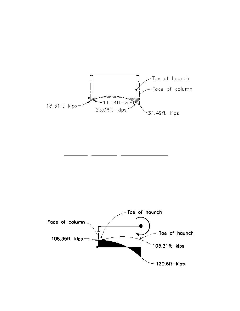
The resulting moment diagram, showing moments at the face of column and at the toe of the haunch, is as
follows;
1-ft-kip = 1.36KN-m
By inspection of this diagram, it is clear that a plastic hinge will form on the right side of the beam first
because the moments are greatest at this location (with increased loading, the moments will increase
proportionately until yielding occurs).
The stress ratio on the right side is;
23.06ft - kips (12"/1' ) / 35.3 - in3
M toe / S x,toe
σ toe- of - haunch
=
=
= 1.2
O.K.
31.49 ft - kips (12"/1' ) / 58 - in3
σ face- of - column M face / S x,haunch
The left side was investigated by placing a plastic hinge at the assumed hinge location on the right side and
analyzing the resulting configuration. The lateral load was increased until yielding occurred at the toe of
the haunch on the left side.
M p = Z x Fy = 40.2 - in3 (36ksi) = 120.6ft - kips (164KN-m)
M y = S x Fy = 35.3 - in3 (36ksi) = 106ft - kips (144KN-m)
The resulting moment diagram, showing moments at the face of column and at the toe of the haunch, is as
follows;
1-ft-kip = 1.36KN-m
H4-25


 Previous Page
