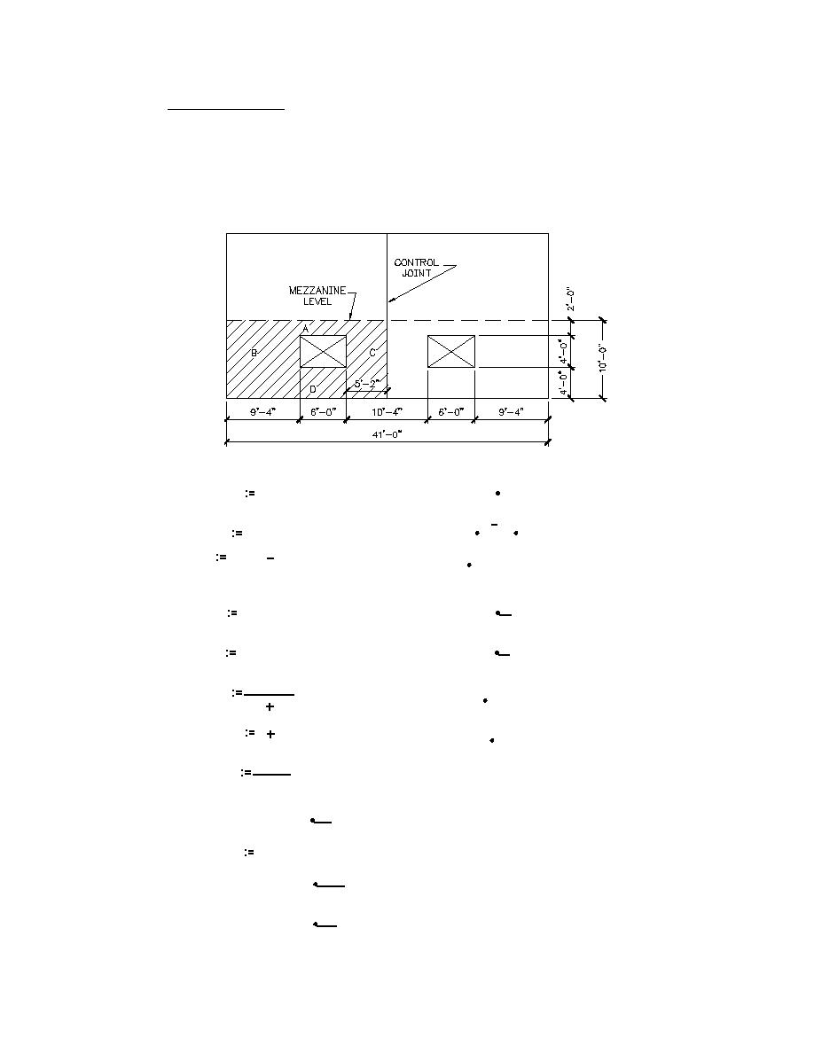
Typical Exterior Wall
The rigidity of the exterior wall is based on the height of the wall below the rigid mezzanine diaphragm.
The walls are assumed to act as separate units between control joints. The wall is symmetric about the
control joint, therefore, the rigidity of the cross-hatched portion of the wall is used for both wall areas.
Recommended control joint spacing is taken from Table 4-1 of TM 5-809-3. All of the CMU shear walls
have horizontal joint reinforcement of 2-#9 wires at every other course (16"). The recommended
maximum ratio of panel length to wall height is 3 with a maximum spacing of 24' The exterior walls have
.
a 10'unsupported height; 3 x 10 = 30 > 24'Use 24'
.
1 inch = 25.4 mm
1 foot = 0.305m
Deflection of solid wall ABCD:
∆ c( 10.ft ,20.5.ft )
∆ abcd
∆ abcd = 0.00026 in
Subtract strip BC:
5
∆ bc ∆ f( 4.ft ,20.5.ft )
∆ bc = 7.8829 10
in
∆
∆ abcd
∆ bc
∆ = 0.00018 in
Add back in piers B & C
1
R f( 4.ft ,9.33.ft )
R b = 5509.26578
Rb
in
1
R f( 4.ft ,5.17.ft )
R c = 2700.94107
Rc
in
1
∆ bc
∆ bc = 0.00012 in
Rb
Rc
∆ abcd
∆
∆ bc
∆ abcd = 0.0003 in
1.kip
R wall
∆ abcd
kip
R wall = 3340.95897
in
2.R wall
R total
Add the two wall segments
1 kip
R total = 6681.91794
This value is kips per inch, (6682 kips / in)
in
KN
R total = 1170.15584
mm
H1-19


 Previous Page
