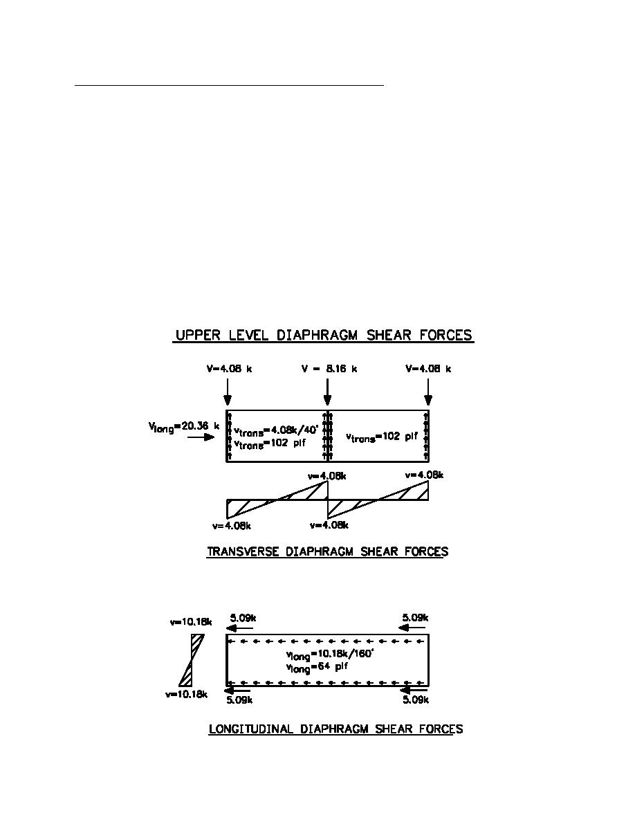
Distribute upper roof diaphragm shear forces to vertical resisting elements
The shear force from the upper roof diaphragm is distributed to the vertical elements based on tributary areas. In the
transverse direction, each of the end exterior CMU shear walls resists of the roof shear while the interior CMU
wall resist of the roof shear. The upper roof shear force in the longitudinal direction is assumed to be resisted by
each of the braced frame bays evenly. Therefore, each bay will resist of the roof shear.
Transverse:
Shear to each exterior CMU wall = (1/4)(16.32kips) = 4.08 kips (18.15 KN)
Shear to interior CMU firewall = (1/2)(16.32kips) = 8.16 kips (36.30 KN)
The unit shear force in the diaphragm, v, will be the maximum at the shear walls.
v = shear at walls / diaphragm depth
v = 4.08 kips / 40'= 102 plf (1.49 KN/m)
Longitudinal:
Shear to each braced frame bay = (1/4)(20.36kips) = 5.09 kips / braced bay (22.64 KN)
The diaphragm is assumed to act as a simply supported beam spanning between the braced frame
wall lines. The maximum shear in the diaphragm is located at the edges. The unit diaphragm
shear , v = 2(5.09kips)/160'= 64 plf (933 N/m)
1 kip = 4.448 KN
1 plf = 14.59 N/m
H1-16


 Previous Page
