TM 5-813-3/AFM 88-10, Vol 3
tion-type CO2 feeder and apply CO2 solution in conduit
therefore, be in the range of approximately 3000 to
carrying the combined effluents from the secondary
4900 gpm. A critical design factor is the upflow rate at
flocculator-clarifier basins.
the slurry separation level in the clarification zone.
k. Carbon dioxide. In developing this example, it
This should not exceed approximately 1.5 gpm per
was assumed that carbon dioxide would be purchased
square foot (2160 gpd per square foot) for lime-soda
in liquid form, stored in a refrigerated storage tank,
softening plants treating turbid surface water. For
equipped with a vaporizer, and applied by means of
this example, basin area at the slurry separation level
solution-feed equipment generally similar to that em-
should be at least 980/1.5 or 653 square feet. Radial
ployed for the measurement and application of chlo-
launders with submerged orifices are commonly pro-
rine. Other sources of carbon dioxide could be used.
vided to collect the clarified water. Lime and soda ash
Carbon dioxide may be generated on-site by combus-
for coagulation and softening are added to the mixing
--
tion of oil, gas, or coke. A compressor and recarbona-
section of each solids-contact basin.
tion basin containing a diffusion system are required
h. First-stage recarbonation. Provide two identical
to apply the CO2 thus generated to the water.
5 feet by 5 feet recarbonation-mixing basins, having a
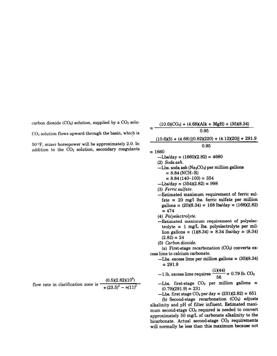
1. Chemical requirements for softening process.
water depth of 5 feet, and located as shown on figure
(1) Lime.
B-2. Flow from the division structure should enter
Lbs. 95%quicklime (CaO)per million gallons
near bottom of each basin where it will be mixed with
tion feeder. The combined flow of softened water and
-1
mechanically mixed. For a G value of 500 see at
(ferric sulfate and polymer) are applied in these mixing
basins. Means for recycling of ferric sulfate-calcium
carbonate sludge to these mixing basins should be pro-
vided. This sludge is pumped from the underflow of
tack of the secondary flocculator-clarifiers and dis-
charged to the corresponding recarbonation-mixing
basin at a maximum rate of approximately 200 gpm.
Sludge pumps should be equipped with timers so that
Pump operation can be started and stopped at the in-
tervals found to be best during plant operation.
i. Secondary flocculation and clarification. Provide
two identical circular center-feed basins with an inner
flocculation zone, an outer clarification zone, and me-
chanical sludge removal equipment. Each basin should
Provide at 50 percent of design flow a total detention
time of 2-1/2 hours, 30 minutes for flocculation and 2
hours for sedimentation. Value flocculation zone is
(30)(60)(0.5)(4.36) or 3,920 cubic feet. Volume clarifi-
cation zone is (120)(60)(0.5)(4.36) or 15,700 cubic feet.
For an average depth of 10 feet in the flocculation
zone and 12 feet in the sedimentation zone, the re-
quired construction diameters are 22 feet for the floc-
culation zone and 47 feet for the entire basin. Over-
or 1040 gpd per square foot, (0.72 gpm per square
foot), The flocculator should have a variable speed
drive and should provide a G value of approximately
-
50 see l at mid-speed and a water temperature of
50F.
j. Second-stage recarbonation. Prior to filtration,
provide an additional stage of recarbonation. Use solu-
B-9


 Previous Page
