TM 5-813-3/AFM 88-10, Vol 3
valves, surface and backwash facilities, and operating
Location
consoles. provide essential instrumentation for each
Water level upstream, first-stage flow divi-
filter. Provide sampling taps for each filter. Plant lay-
sion weir
out and hydraulic design should be such that addition-
Water level downstream, first-stage flow
al filters can be readily added as required.
division weir
i. Clearwell. Clearwell (filtered water storage)
(Loss: raw water pipe friction + velocity
capacity should be related to the available or proposed
head in pipe
distribution system storage (ground and elevated). As
Water level in first-stage rapid-mix basin
an approximation for this design example, clearwell
(Loss: rapid-mix to first-stage flocculator-
capacity of at least 0.6 million gallons could be pro-
clarifier
vided. This is about 25 percent of the plant's daily pro-
Water level in first-stage flocculator basin
duction when operating at 2.2 mgd (design capacity).
(Loss: flocculator to sedimentation basin
Greater clearwell capacity may prove advantageous
Water level in first-stage sedimentation
depending on water demand patterns and plant oper-
basin
ating schedule. The clearwell is commonly located
First-stage sedimentation basin overflow
adjacent to the filters and at an elevation permitting
level
gravity flow to it. This usually requires an under-
(Loss: sedimentation basin weirs, launder
ground structure. An alternative arrangement consists
and piping to second-stage division struc-
of a sump following the filters, equipped with auto-
ture
matically controlled transfer pumps, which discharge
(Loss: second-stage division structure
to an above-ground tank or basin. Underground clear-
Water level in second-stage rapid-mix basin
wells are commonly constructed or reinforced con-
(Loss: rapid-mix to second-stage floccula-
crete. For above-ground installations, steel tanks can
tor clarifier
be used. Regardless of the arrangement, the clearwell
Water level in second-stage flocculator
should be an independent structure, watertight, and
(Loss: flocculator to sedimentation basin
protected against birds, animals and insects. Vents
Water level in second-stage sedimentation
must be installed and protected against surface and
basin
rainwater entry, birds, insects and animals. A pro-
Second-stage sedimentation basin overflow
tected, free-discharge, overflow should also be pro-
level
vided. The overflow must not be connected to any
(Loss: sedimentation basin weirs, launder
sewer or drain. Access to the interior of the clearwell is
and filter influent piping
required.
Water level in filters
The access opening should be curbed at least 6 inches
Top of anthracite (- 7.00)
above the roof surface and be equipped with a hinged,
Filter operating floor level (+3.67)
overlapping, watertight, locking cover. As a general
(Filter freeboard at second-stage basin over-
rule, the clearwell should be located at least 50 feet
flow level
from sewers or drains. The area around the clearwell
Bottom of filter cells (- 15.00)
should be fenced and the site graded so that surface
(Maximum loss through filter media, gravel
drainage is away from the structure. Where winters
underdrains, effluent piping and controls
are severe, special consideration must be given to the
Maximum water level in clearwell
design of vents and overflows to prevent freeze-up as a
(Overall head loss during emergency oper-
result of vapor condensation. A water level sensing in-
ation: first-stage division structure--
strument with readout in the plant control center
maximum clearwell level
should be provided. This can operate in conjunction
By utilizing higher-than-normal chemical dosages, the
with the previously described maximum level control-
plant can be operated under emergency overload con-
alarm circulation and lengthened chlorine contact
ditions and still produce water meeting drinking water
time.
standards. In deriving the above data, the following
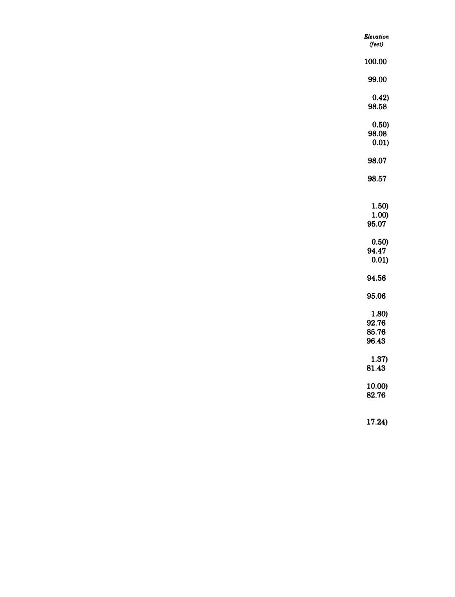
j. Hydraulic profile. The hydraulic interrelationship
emergency conditions were assumed:
of major plant units must be carefully considered. In
(1) All raw water pumps are operated, giving a
general, the hydraulic design of the plant should be on
raw water flow of 3.3 mgd, which is 1.5 times nominal
the side of ample flow capacity so that, under emer-
design rate.
gency conditions, water can be treated and filtered at
(2) Both first- and second-stage rapid mix, floc-
considerably more than the normal rate with all filters
culation, and sedimentation units on one side of plant
in service. The approximate elevation data, given in
are out of service.
the following tabulation, establish the emergency-
-
(3) Reference elevation of water in first-stage flow
operation hydraulic profile:
B-4


 Previous Page
