TM 5-818-5/AFM 88-5, Chap 6/NAVFAC P-418
U. S. Army Corps of Engineers
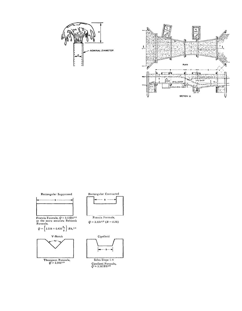
Figure F-8. Fountain flow measurement.
Courtesy of Fairbanks Morse, Inc., Pump Division
Figure F-11. Plan and elevation of the Parshall measuring flume.
smooth and parallel, and extend throughout the region
of flow associated with the weir. Complete aeration of
the nappe is required for rectangular suppressed
weirs. The approach channel should be of uniform sec-
tion and of a length at least 15 times the maximum
head on the weir. Smooth flow to and over the weir is
essential to determination of accurate rates of flow.
The head on the weir should be measured with a hook
gage located in a stilling box at the side of the ap-
proach channel. The communication pipe to the still-
(Courtesy of Fairbanks Morse. Inc., Pump Division)
ing box should be about 1 inches in diameter and
should be flush with the side of the channel. Formulas
Figure F-9. Rectangular suppressed weir.
for calculating the flow over various types of weirs are
shown in figure F-10.
b. Parshall flume. Flow in an open channel may also
be measured with a Parshall flume (fig. F-11). The
head drop through the flume is measured by two gates
(fig. F-11); but if the depth of water at the lower gage
is less than 70 percent of the depth at the upper gage,
the flow is termed "free" and the discharge can be de-
termined by reading the upstream hook gage alone.
The construction and dimensions of a Parshall flume
are shown in figure F-11 and table F-2. The free flow
discharge of a Parshall flume is given in table F-3.
(Courtesy of Fairbanks Morse, Inc., Pump Division)
Figure F-10. Formulas for computing flow over various types of weirs.
F-5


 Previous Page
