TM 5-818-5/AFM 88-5, Chap 6/NAVFAC P-418
thickness and freeboard must be subtracted from the
measured y to obtain the correct value of y.
b. Fountain flow. The flow from a vertical pipe can
be approximated by measuring the height of the use of
and
the stream of water above the top of the pipe (fig.
v = velocity at center of concentric rings of equal
F-8). Two types of flow must be recognized when deal-
area
ing with fountain flow. At low crest heights, the dis-
n = number of concentric rings
charge has the character of weir flow, while at high
crest heights the discharge has the character of jet
F-3. Approximate measurement meth-
flow. Intermediate values result in erratic flow with
ods.
respect to the height of the crest H.
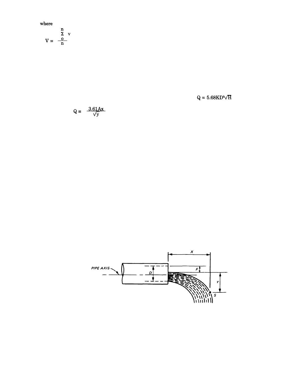
a. Jet flow. Flow from a pipe can be determined ap-
(1) Where the flow exhibits jet character, it can be
proximately by measuring a point on the arc of the
computed from
stream of water emerging from the pipe (fig. F-6),
(F-5)
using the following equation:
where
Q = flow, gallons, per minute
(F-4)
K = constant varying from 0.87 to 0.97 for pipes 2
where
to 6 inches in diameter and h = 6 to 24 inches
Q = flow, gallons per minute
D = inside pipe diameter, inches
A = area of stream of water at end of pipe in
H = vertical height of water jet, inches
square inches. If the pipe is not flowing full,
Where the flow exhibits weir character, it can be ap-
the value of A is the cross-sectional area of the
proximated by using the Francis Formula, Q = 3.33
water jet where it emerges from the pipe, The
Bh3/2, with B being the circumference of the pipe.
area of the stream can be obtained by multi-
(2) Some values of fountain flow for various nom-
plying the area of the pipe times the Effective
inal pipe sizes and heights of crest are given in table
Area Factor (EAF) in figure F-7 using the
F-1.
ratio of the freeboard to the inside diameter of
F-4. Open channel flows.
the pipe.
a. Weirs. Flow in open channels can be measured by
x = distance along axis of the discharge pipe
through which the stream of water moves
weirs constructed in the channel. Certain dimensional
from the end of the pipe to a point(s), inches
relations should be recognized in constructing a weir
to obtain the most accurate flow measurements as
y = distance perpendicular to the axis of the dis-
shown in figure F-9. The weir plate should be a non-
charge pipe through which the stream of
corrosive metal about 1/4 inch thick with the crest 1/8
water drops, measured from the top or surface
inch wide, and the downstream portion of the plate
of the stream of water to point(s), inches
beveled at 45 degrees. The crest should be smooth, and
It should be noted that the x and y distances are meas-
the plate should be mounted in a vertical plane perpen-
ured from the top of the stream of water; if y is meas-
dicular to the flow. The channel walls should be
ured in the field from the top of the pipe, the pipe
U. S. Army Corps of Engineers
Figure F-6. Flow from pipe.
F-3


 Previous Page
