TM 5-815-5/AFM 88-5, Chap 6/NAVFAC P-418
APPENDIX F
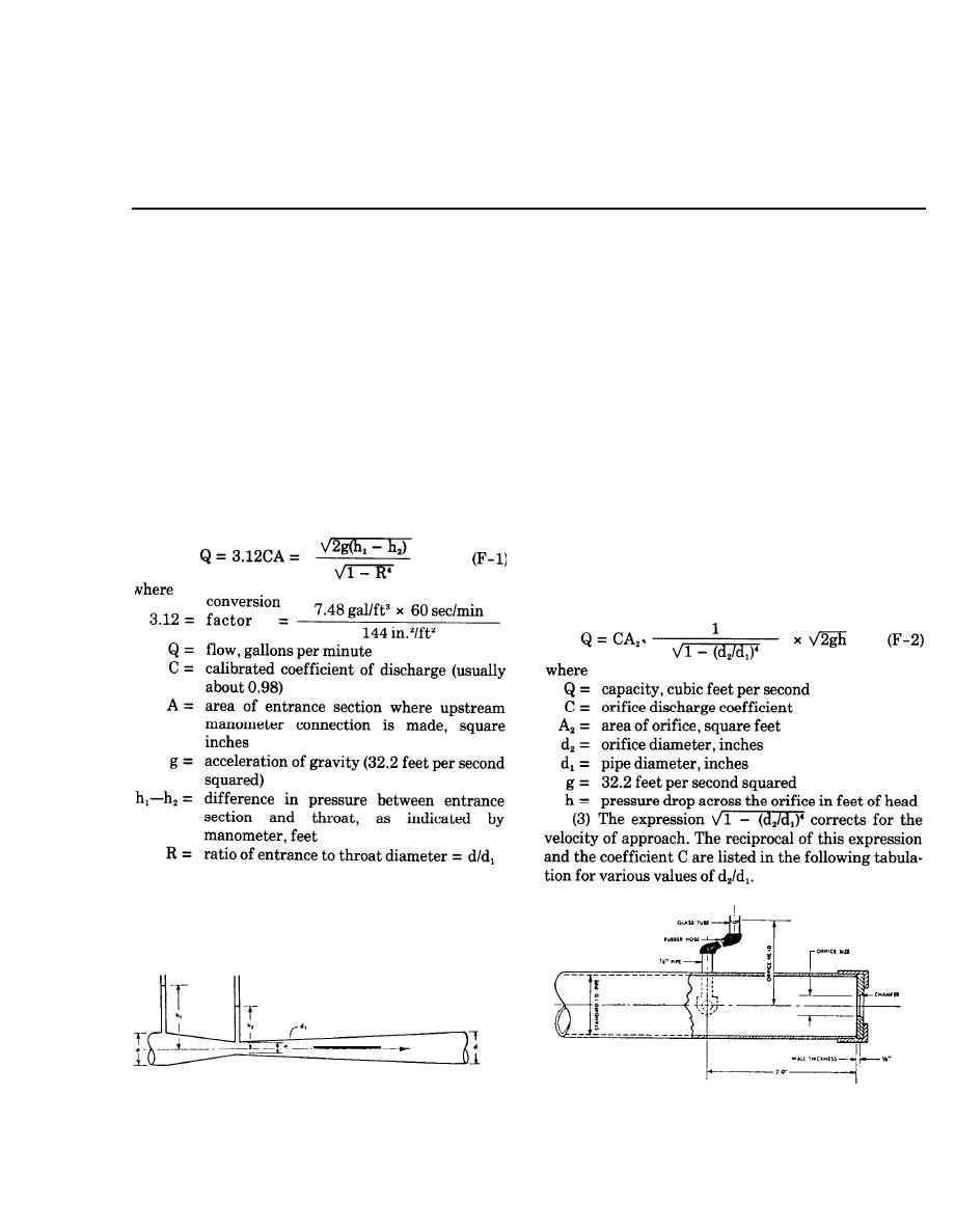
WELL AND TOTAL DISCHARGE MEASUREMENTS
F-1. General. The simplest method for determin-
b. Orifices.
ing the flow from a pump is to measure the volume of
(1) The flow from a pipe under pressure can be
the discharge during a known period of time by collect-
conveniently measured by installation of an orifice on
ing the water in a container of known size. However,
the end of the pipe (fig. F-2), or by insertion of an ori-
this method is practical only for pumps of small capac-
fice plate between two flanges in the pipe (fig. F-3).
ity; other techniques must be used to measure larger
The pressure tap back of the orifice should be drilled at
flows.
right angles to the inside of the pipe and should be per-
fectly smooth as illustrated in figure F-4. A rubber
F-2. Pipe-flow measurements.
tube and glass or plastic pipe may be used to measure
a. Venturi meter. The flow from a dewatering sys-
the pressure head. The diameter of the orifice plate
tem can be accurately measured by means of a venturi
should be accurate to 0.01 inch; the edge of the plate
meter installed in the discharge line. In order to obtain
should be square and sharp, should have a thickness of
accurate measurements, the meter should be located
/8 inch, and should be chamfered at 45 degrees as
1
about 10 pipe diameters from any elbow or fitting, and
shown in figure F-2. The approach pipe must be
the pipe must be flowing full of water. The flow
smooth, straight, and horizontal; it must flow full, and
through a venturi meter can be computed from
the orifice should be located at least eight pipe diam-
eters from any valves or fittings. The flow for various
sized cap orifice-pipe combinations can be obtained
from figure F-5.
(2) The flow through an orifice in a pipe can be
computed from
The pressures h1 and h2 may be taken as illustrated in
figure F-1 for low pressures, or by a differential mer-
cury manometer for high pressures. Gages may be
used but will be less accurate.
(Courtesy of Fairbanks Morse. Inc., Pump Division)
(Courtesy of Fairbanks Morse. Inc., Pump Division)
Figure F-1. Venturi meter.
Figure F-2. Pipe cap orifice.
F-1


 Previous Page
