TM 5-818-5/AFM 88-5, Chap 6/NAVFAC P-418
1
C
d2/ d1
0.604
1.002
0.25
1.004
0.30
0.605
0.606
1.006
0.35
0.606
1.013
0.40
0.607
1.033
0.50
1.072
0.60
0.608
0.70
0.611
1.146
0.643
1.301
0.80
1.706
0.90
0.710
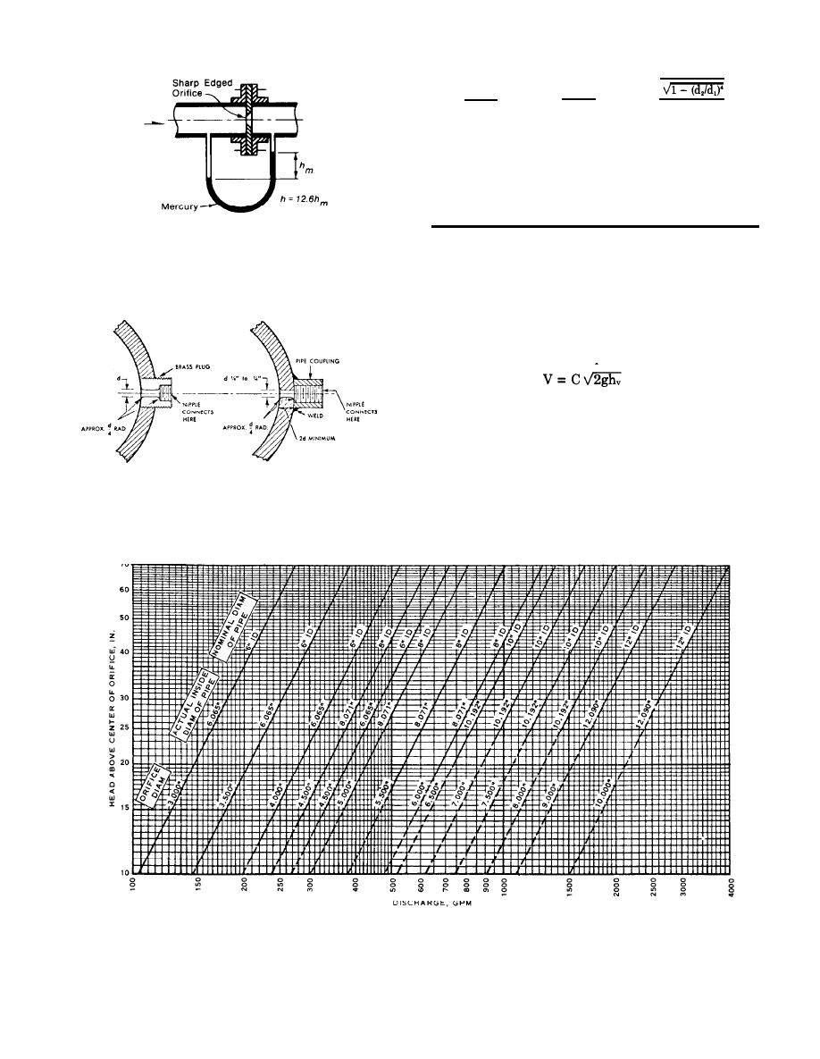
(Courtesy of Fairbanks Morse, Inc., Pump Division)
Note: The diameter of the orifice should never be larger than 80
percent of the pipe diameter in order to obtain a satisfactory pres-
Figure F-3. Orifice in pipe.
sure reading.
c. Pitot tube. The flow in a pipe flowing full can also
be determined by measuring the velocity at different
locations in the pipe with a pitot tube and differential
manometer, and computing the flow. The velocity at
any given point can be computed from
(F-3)
where
V = velocity
C = meter coefficient
g = acceleration of gravity
h = velocity head
The flow is equal to the area of the pipe A times the
(Courtesy of Fairbanks Morse, Inc., Pump Division)
average velocity V, or
(F-3a)
Q = AV
Figure F-4. Approvedpressure taps.
(Courtesy of Fairbanks Morse, Inc., Pump Division)
Figure F-5. Pipe cap orifice chart.
F-2


 Previous Page
