UFC 3-410-04N
25 October 2004
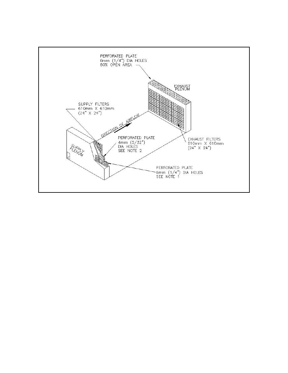
Figure 10-2. Hangar door and exhaust plenum details.
NOTES:
1.
Size open area for an airflow velocity of 10.16 m/s (2,000 fpm) through holes.
2.
Size open area for an airflow velocity of between 3 to 3.5 m/s (600 to 700 fpm)
through holes.
10-3.3
Exhaust Filtration System. See paragraph 9-3.1.2
10-3.4
Auxiliary Walk-in Paint Spray Room. See Chapter 9 for a paint spray
room design.
10-3.5
Storage and Mixing Room. Refer to the ACGIH IV Manual, Paint Mix
Storage Room, VS-75-30 for ventilation system design.
10-3.6
Paint Mixing Hood. See paragraph 9-3.3.
10-4
FANS AND MOTORS. Use explosion proof motor and electrical fixtures for
exhaust fan. Do not place electric motors, which drive exhaust fans, inside hangars or
ducts. See paragraph 2-4.2 for more detailed information about selecting a fan.
10-5
REPLACEMENT AIR. Design the replacement air system to maintain a
neutral air pressure inside the hangar. This will prevent dust from entering the paint
10-3


 Previous Page
