UFC 3-410-04N
25 October 2004
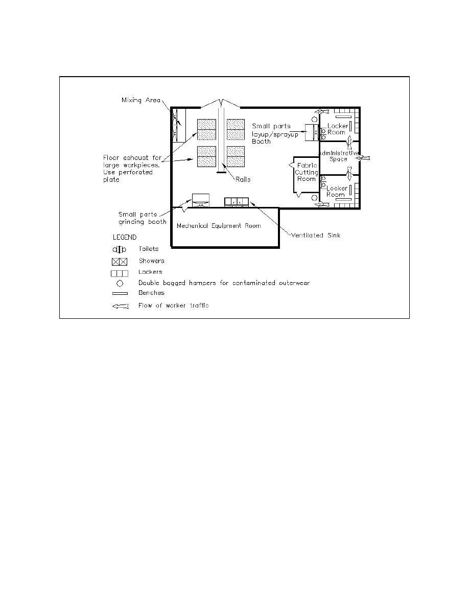
Figure 5-1. Floor plan for FRP facility.
5-4
DESIGN CRITERIA. Design the facility using general technical
requirements in Chapter 2 of this UFC and the specific requirements in this Chapter.
5-4.1
Exhaust Air System. Provide an exhaust system that captures
contaminated air generated during FRP fabrication and repair operations. Refer to
Chapter 2 of this UFC; UFC 3-600-01; NFPA 33, Standard Spray Application Using
Flammable and Combustible Materials; NFPA 68, Guide for Venting Deflagrations;
NFPA 91,Standard for Exhaust Systems for Air Conveying of Materials; NFPA 654, and
the specific requirements of this Chapter.
5-4.2
Hood Design. The sizes and shapes of work pieces in FRP fabrication
and repair facilities vary. Design separate hoods for processes producing only
particulate and only vapor, and both particulate and vapor. Consider a molding system
that completely encloses the work piece if the facility repeatedly manufactures the same
work piece. Design exhaust hoods to enclose all processes to the greatest possible
extent without inhibiting operations. Baffle all exhaust hoods to reduce cross drafts and
improve hood efficiency. Table 5-1 summarizes recommended exhaust hoods, capture
velocities, and air pollution control devices for each operation.
5-2


 Previous Page
