UFC 3-410-04N
25 October 2004
4-3.2.4
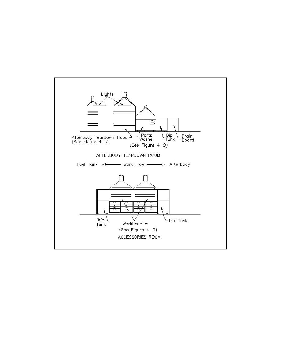
Workflow in Afterbody Teardown Room and Accessories Room.
Figure 4-10 illustrates the workflow in both the afterbody teardown room and the
accessories room with the proper sequence of hoods.
Figure 4-10. MK-48 hood sequence afterbody teardown and accessories rooms.
4-3.2.5
MK-48 Refueling Hood. Before refueling, personnel connect the hoses
from the fueling equipment to the fuel tank. Once the fueling operation has begun, the
operator does not need access to the fuel tank, except to see the hose connections.
Therefore, design an enclosing hood to reduce ventilation rates and decrease the
potential for exposure to a spill during fueling. Design the hood as illustrated in Figure
4-11. Specify the following criteria for the refueling hoods.
a.
A 76 mm (3-in) airfoil rotated inward to prevent turbulence and backflow.
b.
Lighting that is vented and flush mounted in the top of the exhaust hood.
c.
Hood that bolts the floor, using a continuous natural rubber gasket on
hood bottom to create a seal between the hood and the floor.
4-9


 Previous Page
