CEMP-E
TI 809-07
NOVEMBER 1998
F7. SHEAR PANEL PERFORMANCE DOCUMENTATION. Shear panel performance from both
monotonic and cyclic tests shall be documented in terms of load versus deflection plots (TSF versus
DH). Cyclic tests plot load versus deflection to define load versus deflection hysteretic envelopes.
Observations of panel performance and failure progression with respect to lateral displacement shall
be documented in a tabular or other format. Photographs that document these observations shall be
included in the test report. Test results for each specimen tested shall be summarized as indicated in
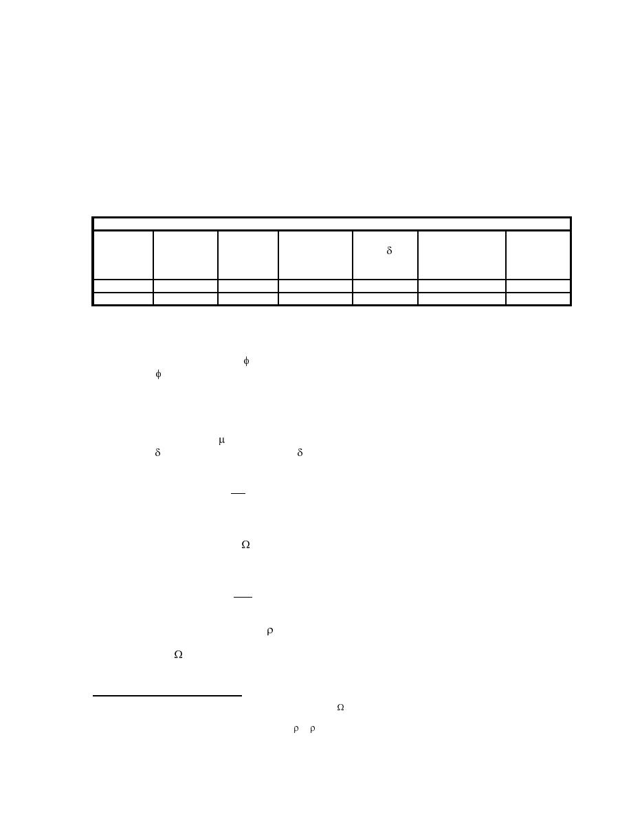
Table F-4. Repeatability of panel performance of a given configuration is critical, so that if only two
cyclic tests are conducted the poorest performance of the two shall form the basis for design.
Therefore special consideration shall be given to large variations in panel performance, especially
failure type or displacement amplitude of each type of failure. Test procedures and results shall be
documented in a test report.
Table F-4. Summary of Test Panel Performance.
Test
Load Type Load Rate Linear Shear Shear Load Shear Deflection
Ultimate
Specimen
(Monotonic
at Ultimate
(mm/min
Shear Load
Stiffness
at y
or Cyclic)
Shear Load
or in/min)
(kN or kips)
(kN/mm) or
Deflection
(mm or inches)
(kips/inch)
(kN or kips)
F8. DESIGN GUIDANCE. The measured load versus deflection data shall be used to define the
design strength and stiffness of the shear panels. Resistance factors for each loading mechanism
shall be defined that recognizes the variation of the shear panel capacity. In other words a panel
shear capacity resistance factor, v, shall reflect the variability of shear capacity of the tested panels.
For example, v = 0.9 if the strength variability is small and mode and displacement of failures are
consistent.
The following criteria shall be defined from the shear panel cyclic test data:
1. The panel ductility, , is the ultimate lateral deflection without loss of lateral or vertical load
capacity, u over yield lateral deflection, y defined as follows:
du
m=
(Eq F-2)
dy
5
2. The panel overstrength, , which is the maximum measured ultimate lateral panel capacity,
Qu over the yield capacity, Qy, defined as follows:
Qu
W=
(Eq F-3)
Qy
6
3. The panel redundancy factor, 1 of the individual shear panel tested . This redundancy can
be seen by comparing shear panel load/deflection data with coupon data, to determine if
overstrength, is due to strain hardening of the primary load-carrying element or due to the
action of a secondary lateral load-resisting element. An example of this would be a panel with
diagonal straps acting as the primary element with the columns effectively working to provide a
5
This should not be confused with the system overstrength factor, 0 defined in FEMA 302, Section 5.2.2 and Table 5.2.2 or
TI 809-07, Equation C-16.
6
This should not be confused with the reliability factor, or x, which is the extent of structural redundancy in the lateral-force
resisting system for an entire story of a building.
F-5


 Previous Page
