CEMP-E
TI 809-07
NOVEMBER 1998
be held constant throughout each test. The top beam shall be held horizontal during all tests, as this
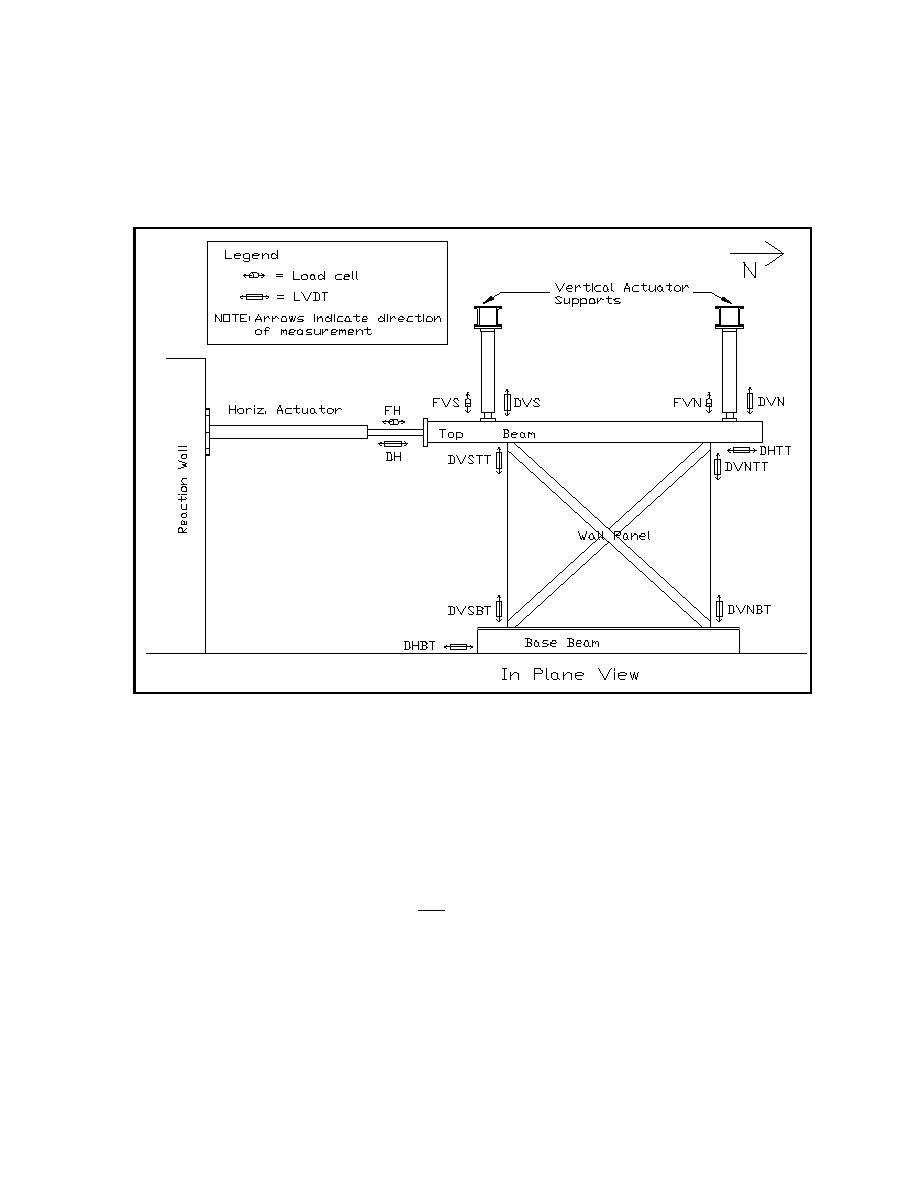
represents the field conditions when the panel is assembled in a building. Figure F-1 shows the test
configuration and instrumentation plan for shear panels tested at USACERL in order to illustrate the
load configuration. In the USACERL tests, stroke control was used to keep the two vertical actuators
at the same length, which held the top beam horizontal. The combined vertical force was held
constant manually.
Figure F-1. Schematic drawing showing sensor locations.
F5. INSTRUMENTATION. Table F-2 defines the instrumentation required for all shear panel tests.
Figure F-1 shows the location and orientation of all sensors. Table F-2 describes the purpose of each
sensor. The purpose of most gages is to ensure that no unwanted motion takes place and for test
st
nd
rd
th
control. The only data used in reporting panel performance are the 1 , 2 , 3 and 4 channels in
Table F-2. The vertical actuator force measurements (FVS and FVN in Table F-2 and Figure F-1) are
required to defined total shear force when deflections reach large amplitudes, at which point the
horizontal components of these forces become significant. This total shear force, TSF is determined
as follows:
DH
TSF = FH - TVFsinarctan
(Eq F-1)
L
Where:
FH = the measured horizontal actuator force (see Table F-2 or Figure F-1).
TVF = the total vertical actuator force, equal to FVS plus FVN (Table F-2 or Figure F-1).
DH = the measured horizontal displacement (Table F-2 or Figure F-1).
L = the length of the vertical actuators, with the vertical load applied, but not horizontal
displacement.
F-2


 Previous Page
