TM 5-809-3/NAVFAC DM-2.9/AFM 88-3, Chap. 3
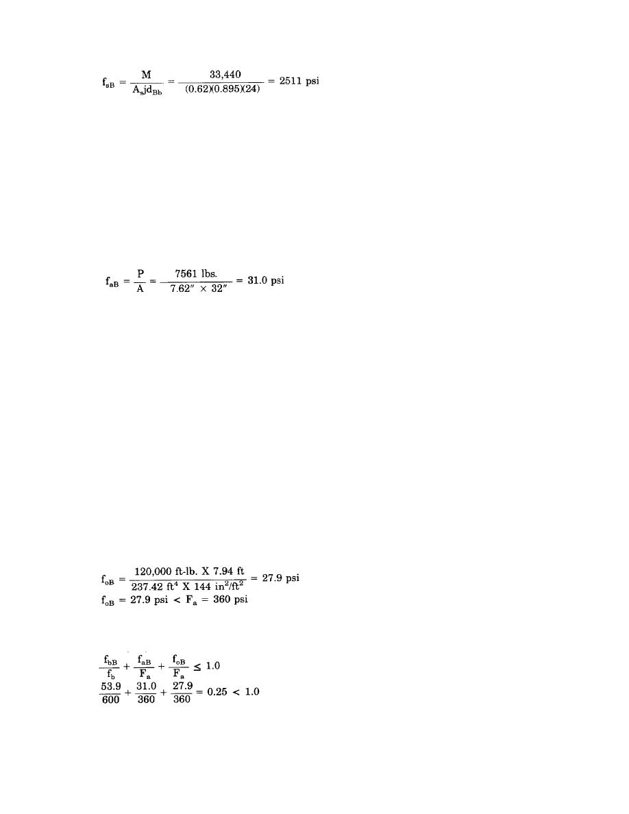
Allowable flexural tensile stress in Pier B, Fs, is determined as follows:
Fs = 24,000 x 1.33 = 32,000 psi (Grade 60 steel)
fsB =2511 psi < Fs = 32,000 psi
...O.K.
Axial Load Check. Since the maximum moment occurs at the top or the bottom of the pier and the axial load
is maximum at the bottom of the pier, the axial load will be determined at the bottom of the pier. The fully
grouted weight of the wall, w2, is 92 psf.
Axial load at the bottom of Pier B, P, is determined as follows:
PTOTAL = PDL + PLL + Wall Wt. to bottom of Pier B
PTOTAL = [(300 lb/ft) + (600 lb/ft)] (4.33 ft)
+ 92psf [(7.33*)(2.67*) + (4.67*)(4.33*)]
= 3900 + 3611 = 7561 lbs.
Axial stress due to axial load in Pier B, faB, is determined as follows:
Allowable axial stress in Pier B, Fa, is determined as follows:
Fa = (0.2 f*m)R
Where:
R = The stress reduction factor.
Since buckling is not a concern at the bottom of the pier, R will be omitted and including wind loading:
Fa = (0.2 f'm) 1.33
= 0.2 (1350) 1.33 = 360 psi
faB = 31.0 psi < Fa = 360 psi
...O.K.
Axial stress on Pier B due to the overturning moment of the entire wall panel, foB, is determined as follows:
foB = MoCB/In,
Where:
Mo = The overturning moment, ft-lbs.
= Vh = 10,000 lb. X 12.0* = 120,000 ft-lb.
CB = Distance from the center of gravity of the net wall section to the centroid of the pier in
question (Pier B). See table 7-1.
In = Moment of inertia of the net wall section
In = G(ICen + AC2) = GAC2 (Because ICen, which is equal to bd3/12, is usually negligible compared
to AC2. Therefore, use In = GAC2. See table 7-1.)
From table 7-1, CB and In are determined and the axial stress on pier B due to overturning, foB, is determined
as follows:
...O.K.
Combined Load Check. The combined effects of flexural, axial, and overturning on pier B can be evaluated
using the unity equation as follows:
...O.K.
Pier C design. The design for out-of-plane wind loadings (not part of this example) require that all cells be
reinforced and fully grouted, thus the cross section of the pier is 3*-4" by 7.62" with 5 bars in each cell. When
checking in-plane shear stresses, the assumed length of the pier, dCv, will be the actual pier length or 3*-4".
When checking in-plane flexural stresses, the assumed effective depth of the beam section, dCb, will be the
7-15


 Previous Page
