TM 5-809-3/NAVFAC DM-2.9/AFM 88-3, Chap. 3
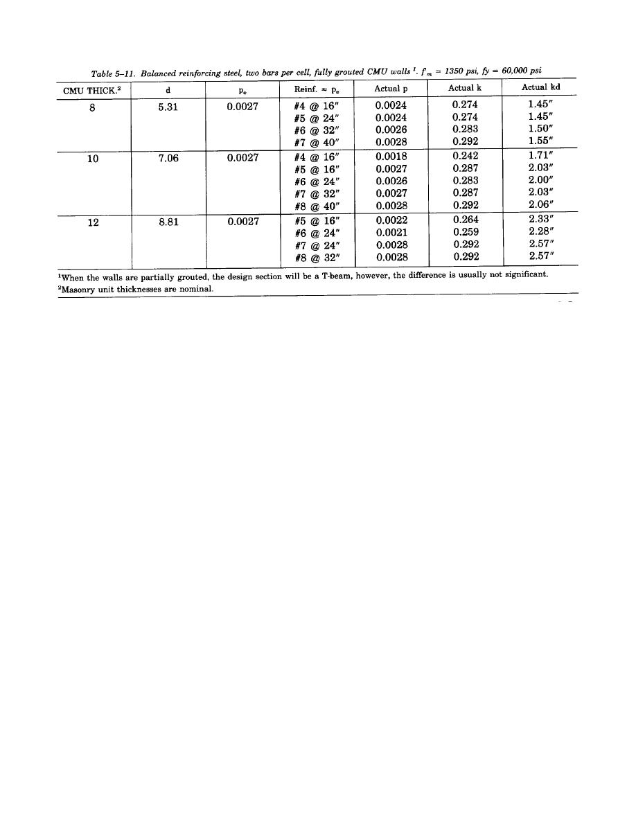
(4) Tables 5-9, 5-10 and 5-11 are applicable to partially and fully grouted CMU walls, as stated. In
partially grouted CMU walls, when the stress block falls below the face shell, that is, when kd > ts (given in
table 5-1), the tables do not apply. With kd > ts, the design will be based on the T-section design method
contained herein. In most cases, when one bar is used per cell, the stress block falls within the face shell and
when two bars are used per cell, the stress block falls outside the face shell. However, for CMU with f'm =
1350 psi, the difference between a T-section beam design and a rectangular section beam design is usually
so insignificant that a rectangular beam design will suffice. When providing two bars per cell, the vertical bars
will be placed outside the horizontal reinforcement. Details will be provided on the drawings showing this
relationship so that the depth to reinforcement assumed in design will be provided during construction. The
details should also provide adequate space to allow grout to be placed and vibrated.
d. Minimum reinforcement. All masonry exterior, bearing and shear walls (structural walls) will be
reinforced as provided below. There are no minimum reinforcement requirements for nonstructural partitions
except around openings as given in chapter 4. In seismic zones 1 through 4, the minimum reinforcement
requirements given in TM 5-809-10/NAVFAC P-355/AFM 88-3, Chapter 13 must also be satisfied.
(1) One vertical reinforcing bar will be provided continuously from support to support at each wall
corner, at each side of each opening, at each side of control joints, at ends of walls, and elsewhere in the wall
panels at a maximum spacing of six feet. This minimum reinforcement will be the same size as the minimum
vertical reinforcement provided for flexural stresses.
(2) Horizontal reinforcement will be provided continuously at floor and roof levels and at the tops of
walls. Horizontal reinforcement will also be provided above and below openings. These bars will extend a
minimum of 40 bar diameters, but not less than 24 inches, past the edges of the opening. For masonry laid
in running bond, the minimum horizontal reinforcement should be one No. 4 bar per bond beam. For masonry
laid in other than running bond, such as stacked bond, the minimum area of horizontal reinforcement placed
in horizontal joints or in bond beams, which are spaced not more than 48 inches on center, will be 0.0007
times the vertical cross sectional area of the wall. Lintel units will not be used in lieu of bond beam units,
since lintel units do not allow passage of the vertical reinforcement. If the wall is founded on a concrete
foundation wall, the required reinforcement at the floor level may be provided in the top of the foundation
wall.
e. Splices of reinforcement. The length of tension and compression lap splices will be 48db, where db is
the diameter of the bar. All other requirements for the development and splices of reinforcement will be in
accordance with ACI 530/ASCE 5.
5-7. Connections between elements. Great care must be taken to properly design and detail connections
between the vertical resisting elements (masonry shear walls) and the horizontal resisting elements
(diaphragms) of the building so that all elements act together to provide an integral structural system. A
positive means of connection will be provided to transfer the diaphragm shear forces into the shear walls. In
designing connections or ties, it is necessary to trace the forces through their load paths and also to make
every connection along each path adequate and consistent with the basic assumptions and distribution of
5-11


 Previous Page
