J-3 PIPE BRACING
a.
Introduction.
(1) Purpose.
The purpose of this example problem is to illustrate the design of pipe bracing
using Chapter 10 and Chapter 6 of FEMA 302 (Components).
(2) Scope.
The problem generally follows the steps in Table 4-5 to analyze the pipe bracing
and anchorage. Typical bracing details may be found in Figure 10-8
Component description.
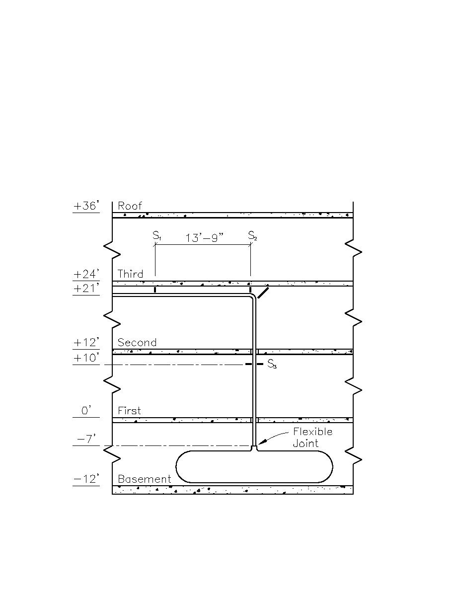
The steel water pipe used in this example problem is a 6-inch (152.4mm) diameter standard wall pipe,
extending from the basement to the second floor of a three story concrete building (see Figure J3-1). The
piping is used to distribute chilled water for HVAC. The building and equipment performance objective is
life safety (LS). Additionally, the equipment is not required to function after an earthquake.
Note: For metric equivalent; 1-ft = 0.30m
Figure J3-1. Water pipe and bracing elevation
J3-1


 Previous Page
