24.7 k / 2 - sides
Ru
=
=
= 2.95" << 10.7" ≤L provided
O.K.
(74.9mm << 271.8mm)
(L w ) req'd
φ n
4.19 k /in
R
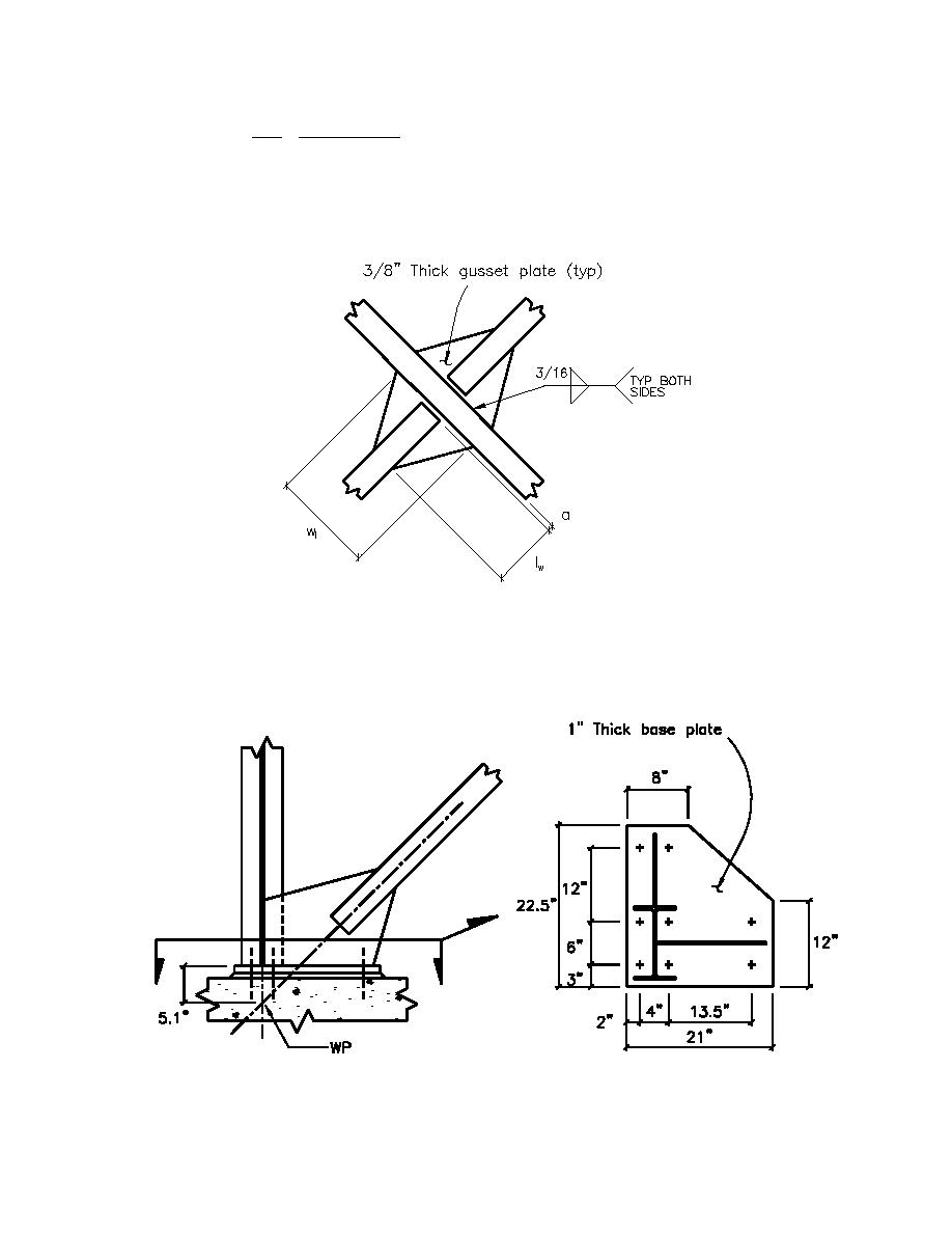
Design brace to brace connection (see Figure J2-9);
Use similar design as used at the brace connection to the column and beam. By inspection, the connection
meets the requirements of shear/tension rupture, tensile capacity, and compressive capacity. Also, buckling
of the gusset plate does not govern because ll is so much less.
Note: For metric equivalents; 1-in = 25.4mm
Figure J2-9. Brace to brace connection
Design gusset plate to column and column base plate (see Figure J2-10);
Use similar design as used at the column to beam connection. All parameters are the same except the
gusset plate attaches to the column base plate instead of the beam.
Note: For metric equivalents; 1-in = 25.4mm
Figure J2-10. Brace to column and column base plate connection
J2-12


 Previous Page
