A.10 Determine member sizes for gravity load effects.
Note: Only supports S1 and S2 support gravity loads. Additionally, connection design will be postponed
until the seismic analysis is complete.
Dead load acting at supports is determined as follows;
a.
Determine unit weight of pipe;
6" φpipe;
19plf
Flanges;
4plf
Supports;
2plf
Water;
20plf
Total =
45plf (0.66KN/m)
b.
Determine required support spacing;
Use 13' 9" (4.19m) for a pinned-pinned rigid pipe per Figure 10-5.
-
c.
Determine dead loads;
WP@S1 = 13.75' 45plf) = 619-lbs (2.75KN)
(
(typical for horizontal spans)
WP@S2 = (13.75'+ 28' (1/2)45plf = 939-lbs (4.18KN)
)
(governs for gravity load design)
Therefore, one design, based on the worst case loading at location S2, will be used throughout for gravity
loads.
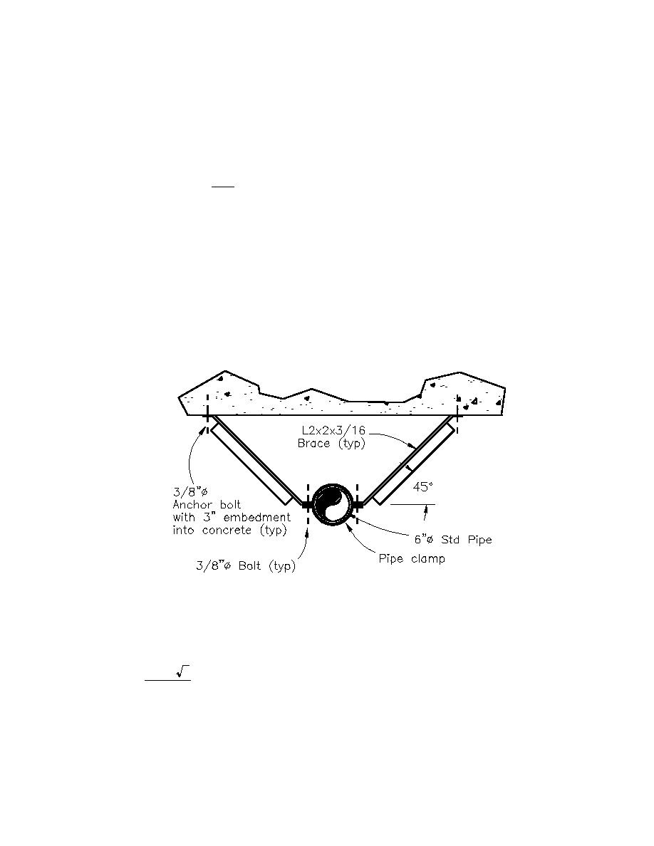
Member design (see Figure J3-2);
Note: For metric equivalent; 1-in = 25.4mm
Figure J3-2. Transverse pipe restraint
Factored dead load acting at support; Pu = 1.4WS2 =1.4(939-lbs) = 1,315-lbs, or 1.32k (5.85KN)
For two braces inclined at 45 degrees (one on either side of pipe), the ultimate load per brace is determined
as;
(1.32 k ) 2
= 0.93k /brace (4.14KN/brace)
Pu =
2
Try L2x2x3/16 (L50.8mmX50.8mmX4.8mm) (Area = 0.715-in2 (461.2mm2)) attached using one 3/8"
(9.53mm) φbolt per connection;
Check yielding on the gross area;
where; φt = 0.90
φt Pn = φt Fy A g
(EQ. D1-1 AISC LRFD)
J3-3


 Previous Page
