1 inch = 25.4 mm
Design of horizontal bracing connections:
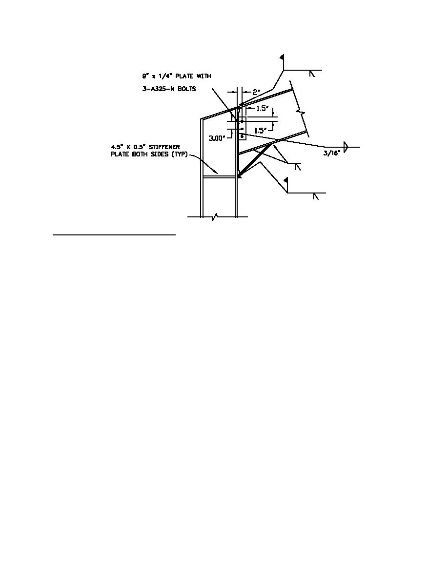
The design of these connections follows Figure 7-22.
Assume plate thickness = " (12.7 mm); thickness of brace = 0.337" (8.56mm); E70XX welds
Design of brace-to-gusset weld;
Design weld capacity to be greater than axial capacity of brace = RyFyAg = 1.5(36ksi)(4.41 in.2) = 238 k (1059 KN)
Minimum weld size = 3/16" (4.76mm)
(AISC LRFD Table J2.4)
Maximum weld size = brace thickness 1/16" = 0.337"-1/16" = 0.28" (7.11mm)
(AISC LRFD Sec. J2.b)
Use " welds (0.25") (6.35mm) 3/16<1/4<0.28, OK
Strength of weld; (per AISC LRFD Sec. J.4 and Table J2.5)
Weld material: φ nw = φte) (0.6 FEXX) = 0.75(0.6)(70ksi)(0.707)(0.25) = 5.6 kips / inch (0.98 KN/mm) (governs)
R
(
Base material: φ nw = φ0.6Fu)t = (0.75)(0.337")(0.6)(58) = 8.8 kips / in (1.54 KN/mm)
R
(
Length of weld required = 238 k / (5.6 k/") = 43" (109cm) (4 welds at connection, use 11" (27.9 cm) welds, 4 x 11
= 44 > 43)
Use 11" (27.9 cm) long " (6.35 mm) fillet welds on all four sides
Check gusset plate capacity
Tension rupture of plate: The tension rupture strength of the plate is based on Whitmore' area. This area is
s
calculated as the product of the plate thickness times the length W, shown in the sketch as a 30 degree angle offset
from the connection line. The tension rupture strength of the plate is designed to exceed the tensile strength of the
brace, 238 kips.
W = 2(11"*tan 30) + 4.5" = 17.2" (43.7 cm)
φPn = φFuAe = 0.75(58)(17.2")(0.5") = 374 k (1664 KN) > 238k (1058 KN) AISC LRFD Eq. D1-2
t
t
Block shear rupture strength of plate:
φ n = φ0.6FyAgv + FuAnt)
R
(
AISC LRFD Eq. J4-3a
φ n = 0.75(0.50)[(0.6)(36)(2 x 11"/cos 30) + (58)(17.2)] = 528 k (2349 KN) > 238 k (1058 KN)
R
H3-57


 Previous Page
