B-11 Determine structural member sizes
Upper roof diaphragm forces - The upper roof diaphragm consists of metal decking. The decking is
(a)
selected from a manufacture' catalog with the required shear and gravity capacities.
s
Transverse direction:
Diaphragm shear force demand = 4.21k (18.7 KN)
Diaphragm shear depth = 60'(18.3m)
Unit shear demand = (4.21k) / (60' = 70 plf (1021 N/m)
)
Longitudinal direction:
Diaphragm shear force demand (grid lines 2-7) = 14.5 k
Diaphragm shear depth (grid lines 2-7) = 90'
Unit shear demand (grid lines 2-7) = (14.5k) / (90' = 161 plf (2.35 KN/m)
)
Diaphragm shear force demand (grid lines 7-8) = 6.42 k
Diaphragm shear depth (grid lines 7-8) = 10'
Unit shear demand (grid lines 7-8) = (6.42k) / (10' = 642 plf (9.37 KN/m)
)
Reinforced Concrete Shear Walls
(b)
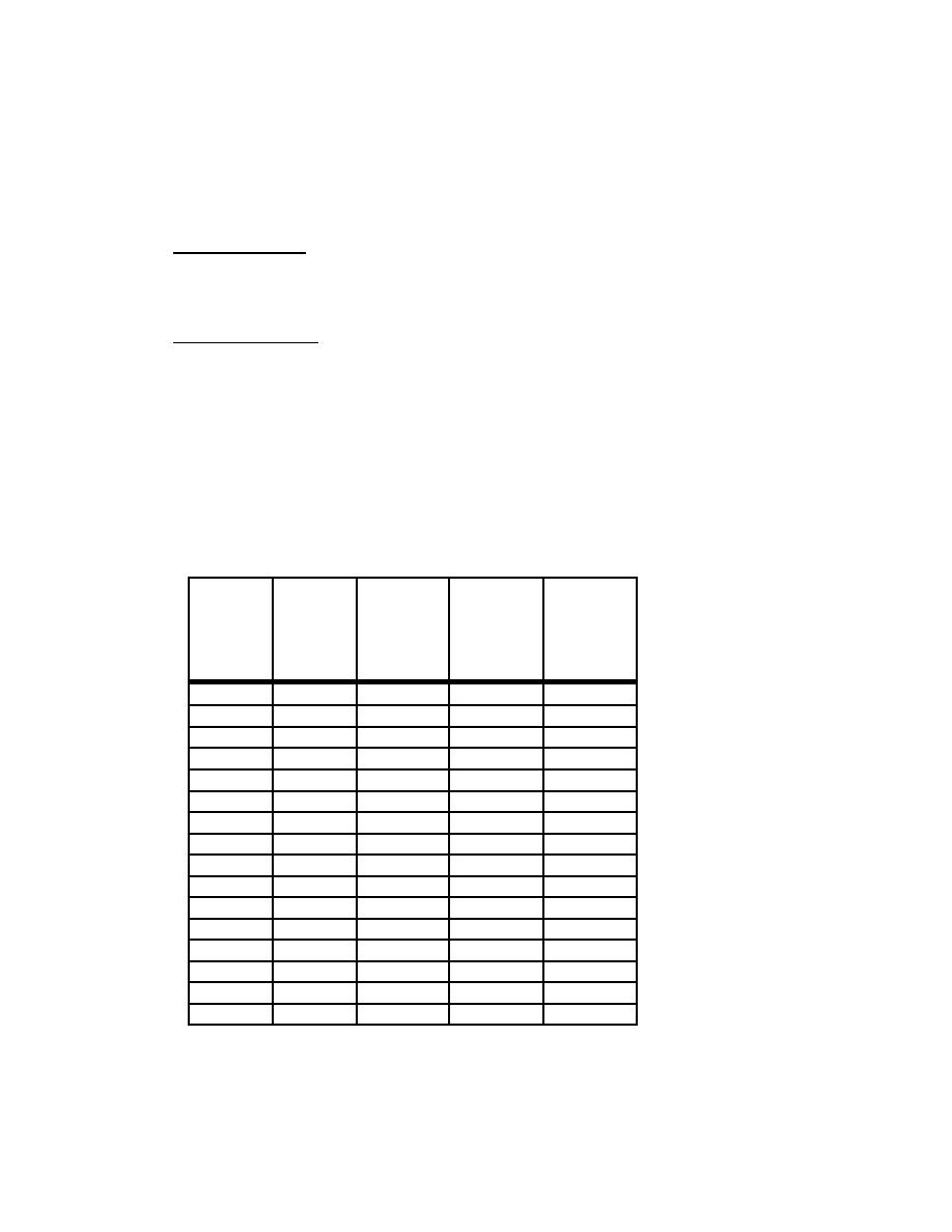
Some of the shear walls resist forces in both the transverse and longitudinal direction due to torsion.
Therefore, per FEMA 302 Section 5.2.7 orthogonal effects must be considered. The walls are checked for
100% of the force in one direction plus 30% in the orthogonal direction.
100%
100%
Element
Total
Total
Transverse Longitudinal Transverse + Longitudinal
+ 30%
Shear
30%
Shear
Longitudinal Transverse
(kips)
(kips)
(kips)
(kips)
Wall 1D-1F
4.3
0.0
4.3
1.3
Wall 2A-2D
30.6
3.2
31.6
12.4
Wall 2F-2I
30.6
3.2
31.6
12.4
Wall 7A-7C
22.3
4.7
23.7
11.4
1 kip 4.448 KN
Wall 7G-7I
22.3
4.7
23.7
11.4
Wall 8A-8I
20.9
3.1
21.8
9.3
Wall D1-D2
0.0
3.0
0.9
3.0
Wall F1-F2
0.0
3.0
0.9
3.0
Wall A2-A7
0.0
37.9
11.4
37.9
Wall I2-I7
0.0
37.9
11.4
37.9
Wall B2-B7
0.0
19.8
5.9
19.8
Wall H2-H7
0.0
19.8
5.9
19.8
Wall A7-A8
0.3
3.3
1.3
3.4
Wall I7-I8
0.3
3.3
1.3
3.4
Wall C7-C8
0.3
9.5
3.2
9.6
Wall G7-G8
0.3
9.5
3.2
9.6
Supported concrete shear / window walls - The supported concrete walls along grid lines B & H transfer
the shear forces from the upper roof diaphragm to the beam collectors along the same grid lines. The
shear from the collectors is then transferred to exterior shear wall lines A & I through horizontal
bracing.
H3-39


 Previous Page
