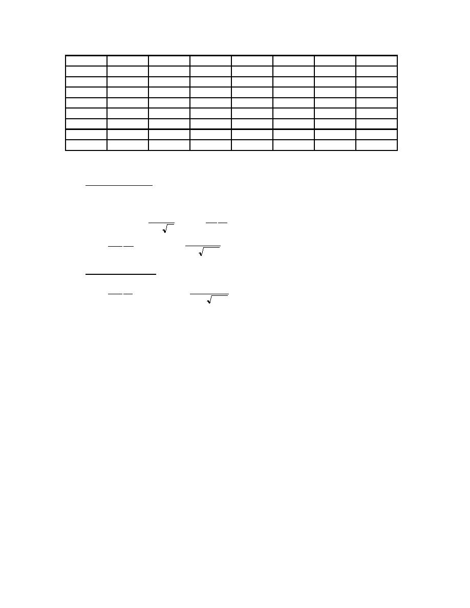
Wall F1-F2
0
0
2.95
0
0
0
2.95
Wall A2-A7
19.8
18.1
0
0
0
0
37.9
Wall I2-I7
19.8
18.1
0
0
0
0
37.9
Wall B2-B7
19.8
0
0
0
0
0
19.8
Wall H2-H7
19.8
0
0
0
0
0
19.8
Wall A7-A8
0
0
0
3.33
0
0
3.33
Wall I7-I8
0
0
0
3.33
0
0
3.33
Wall C7-C8
6.86
0
0
1.97
0
0.67
9.5
Wall G7-G8
6.86
0
0
1.97
0
0.67
9.5
B-8 Determine need for redundancy factor, ρ.
Transverse Direction: Seismic forces in the transverse direction are resisted by a combination of concrete
shear walls and steel moment frames. The majority of the shear force is resisted by shear wall line 8. For
shear walls, rmax is equal to the shear in the most heavily loaded wall multiplied by 10/lw, divided by the
story shear:
V 10
20
, rmax =
ρ=2-
VT l w
rmax A
20
20.9 10
= 0.05 , ρ = 2 -
= - 2.4 , use 1.0
rmax =
106 40'
0.05 8174
Longitudinal Direction Seismic forces in the longitudinal direction are resisted entirely by concrete shear
walls.
20
57.7 10
= 0.065 , ρ = 2 -
= - 1.40 , use 1.0
rmax =
106 84
0.065 8174
B-9 Determine need for overstrength factor, Ω o
The overstrength factor is used for the design of the collectors (beams along lines B and H that support the
upper window/shear walls.
B-10 Calculate combined load effects
The load combinations from ASCE 7-95 are:
(1) 1.4D
(2) 1.2D + 1.6L + 0.5Lr
(3) 1.2D + 0.5L + 1.6Lr
(4) 1.2D + E + 0.5L
(5) 0.9D + E
Where E = ρQE 0.2 SDSD
Eq. 4-4 & 4-5
When specifically required by FEMA 302 (Collectors, their connections, and bracing connections for this
example) the design seismic force is defined by:
E = Ω 0QE 0.2SDSD
Eq. 4-6 & 4-7
0.2SDSD = 0.2(1.0)D = 0.2 D
Therefore, 0.2 will be added to the dead load factor for load combinations 4 and 5.
H3-38


 Previous Page
