Longitudinal Seismic Forces:
Element
Direct Shear Torsional
Total Shear
Force
Shear Force
Force
(kips)
(kips)
(kips)
CMU Wall A1-A2
0.00
0.99
0.99
CMU Wall B1-B2
0.00
0.98
0.98
CMU Firewall E1-E2
0.00
0.00
0.00
CMU Wall H1-H2
0.00
0.98
0.98
CMU Wall I1-I2
0.00
0.99
0.99
1 kip = 4.448 KN
Typical Braced Frame Bay
11.64
0.11
11.75
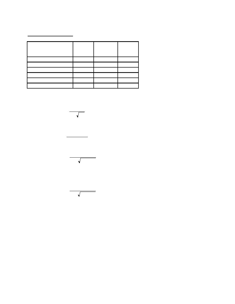
B.8 Determine need for redundancy factor, ρ
20
ρx = 2 -
Eq. 4-1
rmax A x
Transverse Direction (CMU shear walls):
Vmax (10 / l w )
rmax =
Vstory
rmax = (13.22)(10/40)/(47) = 0.07
20
ρx = 2 -
= - 1.5 , use 1.0
0.070 (40)(160)
Longitudinal Direction (Braced frames):
rmax = Vmax / Vstory = (11.75) / 47 = 0.125
20
ρx = 2 -
= 0.0 , use 1.0
0.125 (40)(160)
Both the longitudinal and transverse directions have sufficient redundancy.
B.9 Determine need for overstrength factor, Ω o
FEMA 302 requires the use of the overstrength factor when designing collectors (Sec. 5.2.6.4.2) and the
design of diagonal bracing connections (Sec. 8.6.2). Therefore, the overstrength factor will be used for the
collector force demand in the edge beams and their connections, and the braced frame connection
demands.
H1-35


 Previous Page
